
Light Flashing Car 12 Volt using LM3900

The 12V flasher relay circuit is a crucial component in automotive lighting systems, primarily used for turn signals and hazard lights. The circuit typically consists of a 12V power supply, a flasher relay, and the associated lighting elements, such as incandescent or LED bulbs.
The flasher relay is designed to intermittently connect and disconnect the power supply to the lights, creating a blinking effect. It operates on the principle of thermal or electronic switching, depending on the type of relay used. In a mechanical flasher relay, a bimetallic strip heats up and bends to break the circuit, while in an electronic relay, a transistor or a similar component is used to control the timing of the on/off cycle.
To construct a basic 12V flasher relay circuit, the following components are typically required:
1. A 12V power source, such as a car battery.
2. A flasher relay rated for 12V operation.
3. Two light bulbs (incandescent or LED) to serve as indicators.
4. Connecting wires and a fuse for safety.
The circuit is assembled by connecting the power supply to the input terminal of the flasher relay. The output terminals of the relay are then connected to the light bulbs. A fuse should be placed in line with the power supply to prevent overcurrent situations.
When the circuit is activated, the flasher relay will begin its on/off cycle, causing the connected bulbs to blink. The timing of the blinking can be adjusted by changing the capacitor and resistor values in the circuit, if applicable, in the case of an electronic relay.
This circuit is widely used in automotive applications due to its simplicity and effectiveness in alerting other drivers of the vehicle's intentions, thereby enhancing road safety.If you have evered to use Flasher Relay 12V systematic usual mechanical , for general automobile. Today we try to come to build Circuit Flasher Relay 12V , use. 🔗 External reference
Related Circuits
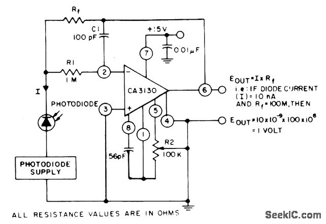
The circuit employs three CA3130 BiMOS operational amplifiers in an application that is sensitive to sub-picoampere input currents. It generates a ground-referenced output voltage that is proportional to the input current flowing through the photodiode. The described circuit utilizes three...
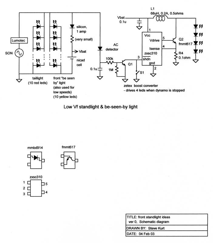
The resistors were not measured precisely, and given their ±5% tolerance, along with a Vref range of 1.2 to 1.3 volts, it is possible to exceed 6 volts in certain scenarios. A discussion arose regarding the effectiveness of these...

The circuit utilizes a 220V AC input, which is processed through a VD1-VD4 bridge rectifier to convert the AC voltage into a DC voltage. This DC voltage is then used to power eight lights labeled H1 to H8. Additionally,...

A microphone (MIC) is used to capture sound, which is then converted into a voltage signal. An operational amplifier (op-amp A) acts as a buffer; one output is directed to a motor drive circuit to control the motor's rotation...
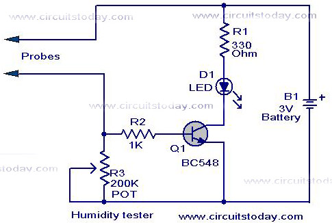
A simple humidity tester circuit using only an LED, a transistor, and a few resistors is explained with a clear circuit schematic. The humidity tester circuit is designed to provide a visual indication of humidity levels using basic electronic components....

The solar orientation circuit employs a comparator with window control to maintain engine idle as long as the two LDRs (light-dependent resistors) are exposed to equal illumination. In this scenario, half the supply voltage is applied to the non-inverting...