
System for solar orientation using common electronic parts

The solar orientation circuit is designed to optimize the alignment of a solar panel or similar device by utilizing two LDRs, which are sensitive to light intensity. The core component of this circuit is a comparator configured to operate with a window control mechanism. In typical operation, both LDRs are connected to a voltage divider, ensuring that when they receive equal illumination, the voltage at the non-inverting input of the comparator (A1) and the inverting input of the second comparator (A2) remains balanced at half the supply voltage.
When the sun moves, the intensity of light on the LDRs changes. This variation in light causes a difference in the resistance of each LDR, which in turn alters the voltage levels at the inputs of the comparators. If one LDR receives more light than the other, the voltage at the non-inverting input of A1 will exceed the threshold set by the inverting input of A2, resulting in a change in the output state of the comparator.
The output of the comparator can be used to control a motor or actuator that adjusts the position of the solar panel. If the output indicates that LDR R1 is receiving more light, the system will trigger the motor to rotate counterclockwise to realign the panel towards the sun. Conversely, if LDR R2 receives more illumination, the system will adjust the motor in the opposite direction. This feedback mechanism allows for continuous adjustment, ensuring that the solar panel remains optimally oriented to capture the maximum amount of sunlight throughout the day.
In summary, the solar orientation circuit effectively utilizes a comparator and LDRs to maintain optimal alignment with the sun, enhancing the efficiency of solar energy collection through automatic adjustments based on light intensity variations.The solar orientation circuit uses a comparator with window control that maintains engine idle as long as the two LDR`s (photoresist) are subjected to the same illumination. In this case, half the voltage is applied to the noninverting input of A1 and A2`s inverting input. When the sun`s position changes, lighting affecting LDR R1 and R2 sites is different, the comparator input voltage window is not half the supply voltage, the comparator output so that the engine generates information for the purposes of direct or rotate counterclockwise counterclockwise. 🔗 External reference
Related Circuits
This month I am making 3 different types of siren circuits based on the 555 timer. The first circuit simulates the siren of a British police car. It uses two 555 timers in the circuit. The 555 on the...
This document presents an improvised circuit model designed to eliminate unwanted DC offset voltage from the output, which affects previously discussed circuits. All prior circuits were intended as low-power Class D amplifier sources suitable for driving headphones through a...

This design circuit functions as an alarm system controlled by a keypad. The core component of the circuit is a single transistor from the BC547 series. The circuit requires a 12-key pad, which has 13 terminals; a matrix type...
An inexpensive control system has been developed, costing less than $70, to enhance the cutting power and accuracy of home-built DC discharge laser systems. This control system employs a technique known as Pulse-Per-Inch (PPI) control, which pulses the laser...
All the adapted numbers of the cipher are in the aforementioned line. To set the adjustment of the cardinal of the code, we accept to set the acceptable affiliation amid the bulge of the 7414 ascribe and the adapted...
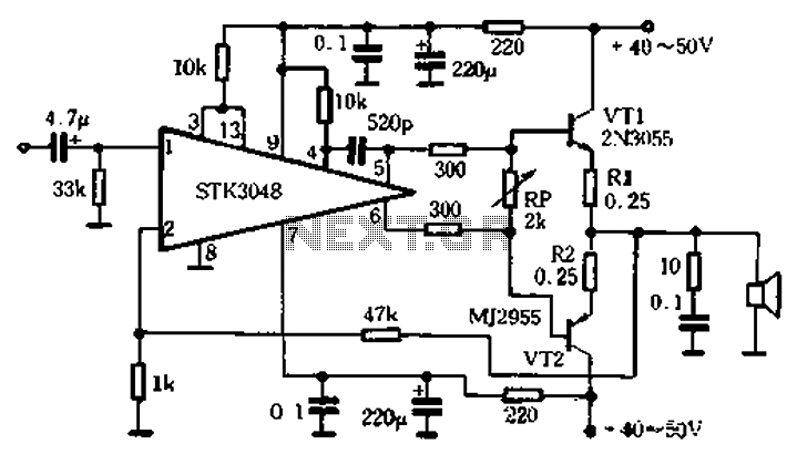
The circuit utilizes the high-power complementary tube STK3048, which operates at high voltage and offers a wide dynamic range. It features an accurate differential input pair, with a common emitter configuration and output terminals connected to a collector constant...