
Light Sensor Switch

Relay output - NC-C-NO
Onboard preset to set the level
Power-On LED indicator
Relay On LED indicator
Power Battery Terminal (PBT) for easy relay output connection
Four mounting holes of 3.2 mm each
PCB dimensions 44 mm x 49 mm
The Light Sensitive Switch circuit utilizes a Light Dependent Resistor (LDR) as the primary sensor to detect ambient light levels. When the light intensity falls below a predetermined threshold, the circuit activates a relay, which can be used to control various loads, such as lights or alarms. The input voltage for this circuit is specified at 12 volts with a current rating of 55 milliamperes, ensuring compatibility with typical low-power applications.
The relay output configuration is designed with Normally Closed (NC), Common (C), and Normally Open (NO) terminals, allowing for versatile control options depending on the application requirements. The onboard preset potentiometer enables fine-tuning of the light sensitivity threshold, providing flexibility in adjusting the activation point of the relay based on environmental conditions.
Two LED indicators are incorporated into the design: a Power-On LED to indicate that the circuit is powered and a Relay On LED to show when the relay is activated. This visual feedback is essential for monitoring the operational status of the device.
For ease of installation and connectivity, the circuit includes Power Battery Terminals (PBT), facilitating straightforward relay output connections. The printed circuit board (PCB) is compact, measuring 44 mm by 49 mm, and features four mounting holes of 3.2 mm each, allowing for secure attachment in various setups. This design ensures that the Light Sensitive Switch is not only functional but also practical for integration into broader electronic projects.Light Sensitive Switch is a simple project which operates a relay when the light falling on the LDR goes below a set point. Input - 12 V @ 55 mA Relay output - NC-C-NO Onboard preset to set the level Power-On LED indicator Relay On LED indicator Power Battery Terminal (PBT) for easy relay output connection Four mounting holes of 3.2 mm each PCB dimensions 44 mm x 49 mm 🔗 External reference
Related Circuits

This page features a circuit that has twenty open collector outputs that turn on one at a time in a continuous sequential manner. The circuit utilizes the 74LSxx family of TTL integrated logic devices. The circuits are designed to...
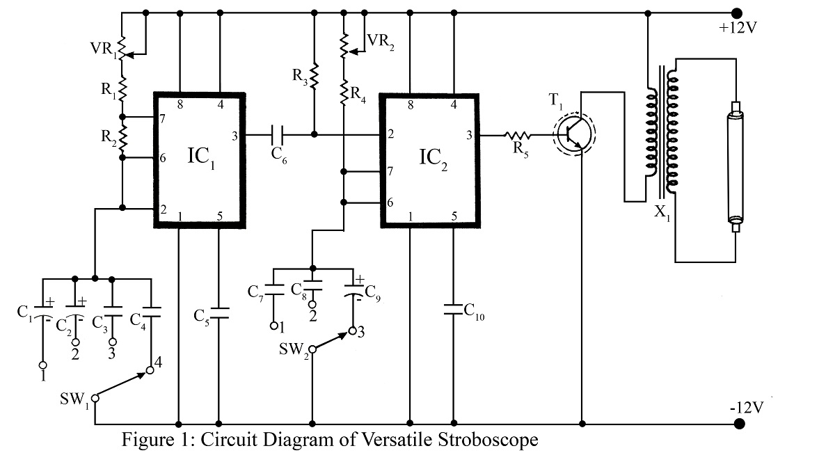
A stroboscope is an instrument used to observe rapidly moving objects with periodic motion as if they are stationary. The strobe light flashes at a frequency that synchronizes with the rotation of a wheel or moving object, creating the...
A light dimmer is quite uncommon in a caravan or on a boat. This document outlines how to create one, allowing for mood adjustment when needed. A light dimmer circuit is an essential component for enhancing the ambiance in confined...
This circuit is constructed around a 555 timer and utilizes very few components. Due to its simplicity, even beginners can easily assemble and use it as a control device. A readily available laser pointer can be employed to operate...

Automatic Headlight Brightness Switch Circuit. Driving on the highway with high-beam headlights can significantly enhance visibility; however, it can also pose a blinding hazard for other drivers. This straightforward circuit can be integrated into your headlight system. This automatic headlight...

An integrated solution for two output channels that simplifies design and enhances reliability. The device, the VNI2140J, integrates on-chip two 45V Power MOSFET channels with a typical Rds(on) of 80mOhm at 25 degrees Celsius. The VNI2140J is a highly integrated...