
Light turning bike using IC LM3909

The bicycle turning light circuit enhances visibility and safety for cyclists during turns. It utilizes a simple yet effective design that incorporates a power supply of 1.5V to activate a timer IC (IC1), which serves as the oscillator. The switch (S1) acts as the user interface, allowing the cyclist to indicate the desired direction of the turn.
In normal operation, the switch remains in the OFF position, ensuring that no power is consumed unnecessarily. When the cyclist intends to turn right, the switch is toggled to the right position, activating the circuit. The oscillator within IC1 generates a square wave signal, which is output at pin 6. This output controls a dual switch (S1/2), enabling the simultaneous flashing of LEDs 3 and 4, thereby signaling to following vehicles the intent to turn.
Conversely, when the switch is moved to the left position, the oscillator's output changes, triggering LEDs 1 and 2 to blink. The frequency of the blinking is adjustable based on the capacitance of capacitor C1, allowing for customization of the visual signal's speed according to user preference or visibility requirements.
This circuit is particularly advantageous for its simplicity and low power consumption, making it suitable for battery-operated bicycles. The design can be further enhanced by incorporating additional features such as a low-voltage cutoff to protect the battery or using more energy-efficient LED technology to extend the operational time between battery replacements. Overall, this bicycle turning light circuit represents a practical solution for improving cyclist safety on the road.Usual already a bicycle has will no Light turning. If want to turn a car may be born dangerous can go up. Because of a car that drive to follow come to don`t know that turn thus. We should enhance the safety gives with one self with building light turning bike circuit this upward. The work of the circuit be in usual time switch S1 will stay in a p osition OFF. If the circuit will turn to the right move switch S1 go to a position Right have power supply 1. 5V, go to at IC1 which be IC1 work oscillator generator come out pin 6 ways change contact switch S1/2 make LED3, LED4 will flasher at the same time conversely. If turn to the left move switch S1 go to at a position Left frequency signal that pin 6 s of IC1 change contact switch S1/2 make LED1, LED2 blink at the same time.
By the speed in something flasher depend on the value of C1 this circuit can work long ago. Because the circuit will work especial when open light turning only. 🔗 External reference
Related Circuits

If you have no idea what is a "strobo", "strobe", "stroboscopy" or whatever way it is called, it is simply a flashing light. It is usually used on police cars, 'disco' places and many interesting applications, including scientific ones....
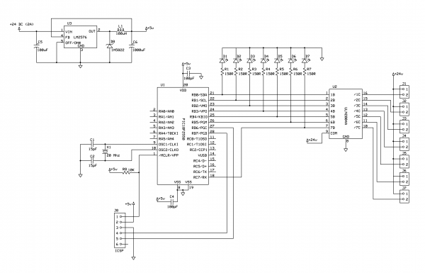
This project demonstrates the construction of a simple LED light string display utilizing seven 24V LED light strings. The project was designed for Christmas 2009 to adorn a balcony with lights. The light strings are widely available, particularly in...
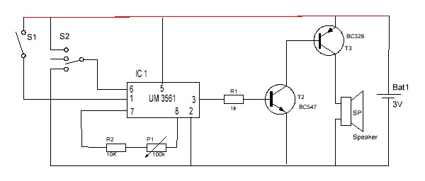
This is a simple audio circuit utilizing the UM3561 for generating melodies that can be employed in toys and various home appliances. It serves as an excellent project for novice beginners. The UM3561 is a dedicated melody generator integrated circuit...
The circuit is a battery charging system powered by Q2, Q6, R8, and D10, which provides constant current to charge the battery. When an external power supply is present, the charging current flows through R8 and D10 to charge...
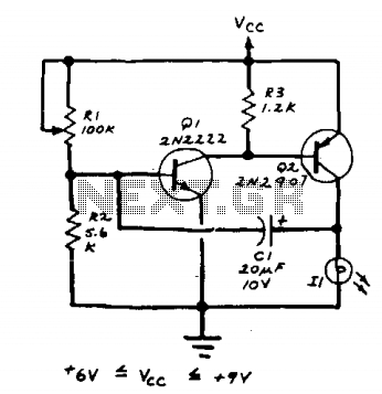
The lamp should be a No. 122, No. 222, or other similar miniature incandescent lamp. R1 adjusts the flash rate. The circuit incorporates a miniature incandescent lamp, specifically a No. 122 or No. 222 type, which serves as the primary...
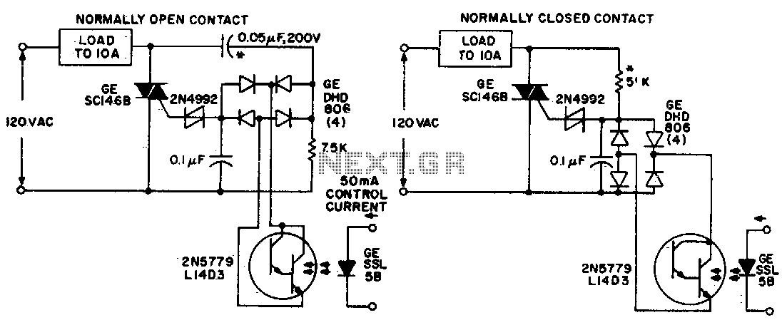
Both circuits utilize the GE SC146B, a 200 V, 10 A Triac for load current contacts. These triacs are activated by standard SBS (2N4992) trigger circuits, which are managed by a photo-Darlington configuration, functioning through the DA806 bridge as...