
Miniature light flasher

The circuit incorporates a miniature incandescent lamp, specifically a No. 122 or No. 222 type, which serves as the primary light source. These lamps are known for their compact size and are commonly used in applications where space is limited. The choice of lamp affects the overall brightness, power consumption, and thermal characteristics of the circuit.
In this configuration, resistor R1 plays a critical role in controlling the flash rate of the lamp. By adjusting the resistance value of R1, the time constant of the circuit can be modified, effectively changing the frequency at which the lamp turns on and off. This adjustment allows for a customizable flashing effect, which can be useful in signaling applications or decorative lighting.
The circuit may include a timing mechanism, such as a capacitor in conjunction with R1, to create a delay in the lamp's on-off cycle. A typical arrangement might involve a simple astable multivibrator or a timer IC, which works in conjunction with R1 to achieve the desired flash rate. The selection of the capacitor value, alongside R1, will determine the duration of the lamp's illumination and the interval of darkness.
Overall, the integration of the No. 122 or No. 222 lamp with R1 for flash rate adjustment forms a versatile lighting solution that can be tailored to specific operational requirements.The lamp should be a No. 122, No. 222 or other similar, miniature incandescent lamp. R1 adjusts the flash rate.
Related Circuits
This circuit operates at 73 MHz and is designed for controlling halogen lights through radio frequency remote control. The primary function is to toggle the power state of a halogen lamp. When the button on the remote control is...

Learn to use microcontrollers to create traffic-light applications. In this project, the AVR-007 microcontroller from Circuits-Home will be utilized. Before developing the program, it is essential to understand the hardware specifications. The project focuses on developing a traffic-light control system...
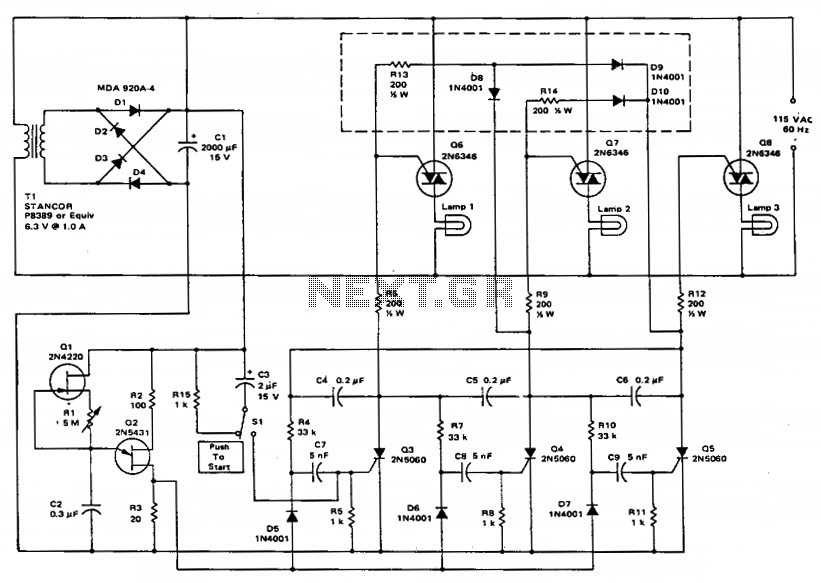
This circuit employs a ring counter consisting of Q3, Q4, and Q5. Q2 functions as an oscillator that sequentially triggers the SCRs Q3, Q4, and Q5. When an SCR is activated, a 0.2 µF capacitor facilitates commutation, turning off...
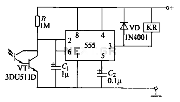
The circuit utilizes a Darlington-type phototransistor as the sensing element, which enhances sensitivity to low light levels, making it suitable for detecting reflected light signals. When the Darlington phototransistor is exposed to light, its resistance decreases, causing the voltage...

This device functions as a module for a Dual Channel IR Remote Control. It serves as a sophisticated switch with a timer for door operation, emphasizing modularity and wireless functionality. The device measures ambient light levels using a CdS...

The following circuit is an enhanced version of the original Lightning Detector designed to operate on a 5-volt supply. This updated circuit incorporates a refined RF section with a single resonance near 300 kHz and increased sensitivity. The use...