
line follower

A line follower robot typically employs a combination of sensors, microcontrollers, and motor drivers to achieve its functionality. The most common sensors used in these robots are infrared (IR) sensors or color sensors. These sensors detect the difference in reflectance between the line and the surrounding surface. When the robot is placed on a track, the sensors continuously monitor the surface beneath it.
The basic operation of a line follower involves the following steps:
1. **Sensor Detection**: The sensors are positioned at the front of the robot, facing downward. When the sensors detect the line, they send signals to the microcontroller indicating whether the line is being followed or if the robot has veered off course.
2. **Microcontroller Processing**: The microcontroller processes the signals received from the sensors. Based on the input, it determines the necessary adjustments to keep the robot centered on the line. For example, if the left sensor detects the line while the right sensor does not, the microcontroller will instruct the motors to steer slightly to the left.
3. **Motor Control**: The robot's movement is controlled by motor drivers that receive commands from the microcontroller. The motors are typically DC motors or stepper motors, which allow for precise control over speed and direction. Adjustments in motor speed and direction are made in real-time, enabling the robot to navigate curves and corners effectively.
4. **Power Supply**: The line follower robot is powered by a battery or a power source that provides the necessary voltage and current to the microcontroller, sensors, and motors. The choice of power supply is crucial for ensuring the robot operates efficiently over extended periods.
5. **Chassis Design**: The physical design of the robot, or chassis, plays a significant role in its performance. A lightweight and compact design helps in maintaining agility and speed, while a stable base ensures that the sensors remain properly aligned with the track.
In summary, a line follower robot is a practical application of autonomous technology, utilizing sensors, microcontrollers, and motor control systems to navigate a predefined path based on color contrast. This technology is widely used in educational robotics and can be further enhanced with additional features such as obstacle detection, speed control, and communication capabilities.A line follower is an autonomous bot that can follow a specific colored line painted on a surface of different contrast, such as white on black.. 🔗 External reference
Related Circuits
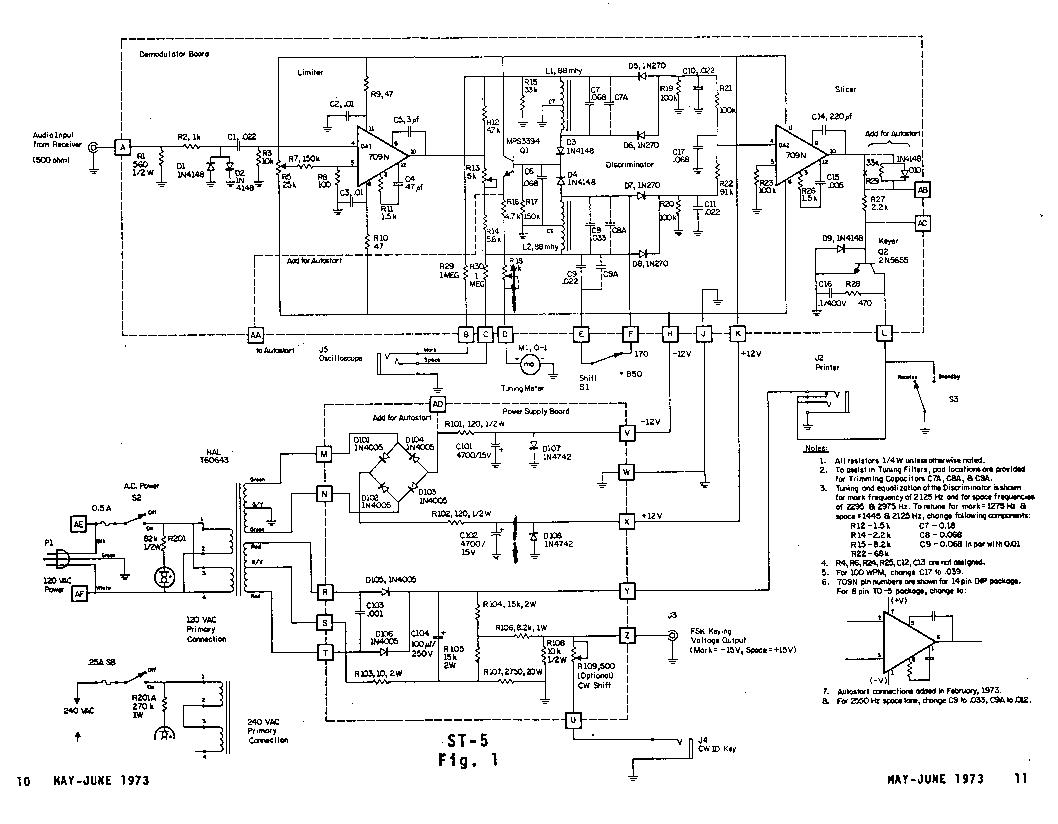
The Mainline ST-5 was introduced in the RTTY Journal in May 1970 and has quickly become a popular demodulator for RTTY. Due to the unavailability of back issues, the original article is being reprinted. Those interested in 100 baud...
Research has been conducted on a project aimed at enhancing understanding of electronics, networking, and programming. The project involves the construction of an online thermometer suitable for applications requiring temperature monitoring. The current work environment is a laboratory where...
The computer needs at least 180 millivolts peak-to-peak and the condenser microphone in my headset produces about 20 millivolts peak-to-peak into a 2.2k load with normal speech levels. There are USB ports on the machines, so I can use...

Cable and xDSL modems are increasingly popular, leading to a need for designs that interface with existing telephones at subscriber locations. The subscriber line interface circuit (SLIC) within the modem must ring the phone and provide loop current during...
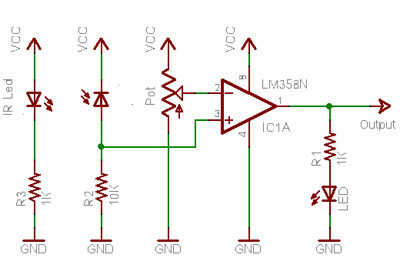
When no light is incident on the diode, it exhibits high impedance (resistance). In contrast, when light strikes the diode, its resistance decreases significantly, approaching a short circuit condition. In the absence of any object in front of the...
A 555 timer and a dual 556 timer are used to generate a basic video signal, as illustrated in the schematic. The first timer operates in astable mode, producing synchronization pulses with a period ranging from 4.7 to 8...