
USB Microphone Line Level Preamp

The circuit described is a condenser microphone preamplifier designed to work with a USB power supply, specifically tailored to amplify the low output voltage of a condenser microphone for effective audio signal processing. The design utilizes a single NPN transistor configured as an AC transconductance amplifier, achieving a gain of approximately 28 dB. The input from the electret microphone, which typically outputs around 20 mV peak-to-peak into a 2.2 kΩ load, is first processed by an inverting FET amplifier, ensuring that the microphone signal is adequately amplified before reaching the NPN transistor.
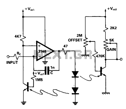
The critical component of the preamplifier is the 100 kΩ feedback resistor, which sets the gain of the transistor. The output voltage of the preamplifier is directly proportional to the input current, with a scale factor indicating that for every 10 µA of input current, the output will be 1 V peak-to-peak. This design ensures that the output signal meets the minimum requirement of 180 mV peak-to-peak for effective computer audio input.
Powering the circuit is achieved through a USB port, providing a stable +5 V supply. The power supply section includes a 2.2 kΩ resistor to pull the drain of the FET high, ensuring proper operation of the microphone element. Additionally, a power supply filter composed of a 100 Ω resistor and a 330 µF capacitor smooths the power supply to the amplifier circuit, minimizing noise and fluctuations.
To prevent potential damage to the output coupling capacitor (4.7 µF), the output of the NPN transistor is connected only to the "Tip" of the audio jack, avoiding issues with reverse voltage that could arise from load resistors present on the "Ring" connection of audio inputs. This precaution is critical in ensuring the longevity and reliability of the preamplifier.
An LED indicator is included in the design, connected in parallel with the USB power supply. The 2.2 kΩ resistor limits the current through the LED, providing a visual indication of power without drawing excessive current, aligning with efficient design principles.
Overall, this circuit effectively amplifies the low-level audio signal from a condenser microphone, making it suitable for interfacing with computer audio inputs while ensuring reliability and power efficiency.The computer needs at least 180 millivolts peak-to-peak and the condenser microphone in my headset produces about 20 millivolts peak-to-peak into a 2.2k load with normal speech levels. There are USB ports on the machines, so I can use that for +5 volts. After a quick look in my parts boxes, I decided to put the input jack and output plug on the end of wires so I would not have to tediously mount them on the enclosure.
The resulting goal was, therefore, a condenser microphone preamp with 19 db gain that is powered from a USB port that can be closed in a small box to hang off the computer and attach to the microphone lead on the headset. The preamplifier itself is a single NPN transistor, and it gives about 28 db of gain. The electrete microphone element includes an inverting FET (Field Effect Transistor) amplifier, and the drain of this FET is the the output of the microphone element. The NPN transistor in the preamp is connected as an AC transconductance amplifier, meaning that its output is a voltage proportional to the AC input current.
The scale factor is set by the 100k feedback resistor. With this value, the amplifier's output is 1 volt peak-to-peak for each 10 microamps peak-to-peak of input current. The drain of the FET in the microphone element needs to be pulled high through a 2.2 k resistor connected to a sufficiently high voltage.
That's the purpose of the 2.2k resistor on the microphone input. The other end of the 2.2k resistor connects to the power supply filter, made of the 100 Ohm and the 330 microfarad capacitor. The output of the power supply filter also provides power to the amplifier circuit. Since the collector of the NPN transistor is at about +1 volt, I was concerned that a load resistor inside a computer, which connected to a positive power supply could cause the 4.7 microfarad output signal coupling capacitor to be subjected to revers voltage, possibly resulting in the preamp not working and the eventual destruction of the 4.7 microfarad capacitor.
I found that many sound cards put the load resistor on the "Ring" connection of the audio input connector. I only connected the output of the amplifier to the "Tip" connection. It does not make sense that there would be a load resistor for a condenser microphone at audio input that does not have sufficient gain to work with a condenser microphone, but there are some switchable inputs, and the precaution of connecting only to the tip would prevent problems.
A green LED is connected across the 5 volts from the USB connector. The 2.2k resistor doesn't light the LED very brightly, but it is just not in my nature to spend a lot of current on indicators unless there is a real need for them to be bright. And this indicator is only to show that the power is flowing from the USB connector. 🔗 External reference
Related Circuits
The 60 Watt linear amplifier is a simple all solid-state circuit using power MOSFET IRF840. The IRF series of power transistors are available in various voltage and power ratings. A single IRF840 can handle a maximum power output of...
A dual optocoupler is utilized in a configuration that maintains the same current across the LEDs. Assuming comparable optocoupler characteristics, the output voltage must match the non-inverting input voltage. Given that the operational amplifier operates within a closed loop,...
The Marshall JTM50 and JMP50 utilize two configurations for the initial preamp stage. One configuration mirrors the design found in Marshall's Bluesbreaker and JTM45, which is identical to the Fender Bassman 5F6-A, except for the tube used: a high-mu...
The circuit described can connect two telephones in parallel and function as a two-line intercom. Typically, a single telephone is connected to a telephone line. When another telephone is needed at a distance, a parallel line is utilized for...
Inquiring about a simple method to bypass the tone controls in the preamplifier, with the understanding that a feedback circuit may be involved, leading to uncertainty. To bypass the tone controls in a preamplifier, one common method is to modify...
A popular project among microcontroller enthusiasts is to build a radio-controlled clock. Tiny receiver boards are available, equipped with a pre-tuned ferrite antenna that receives and demodulates the DCF77 time signal broadcast from Mainflingen in Germany. DCF77 has an...