
Linear frequency meter

The 555 timer in a monostable configuration operates by producing a single output pulse in response to a triggering input. When the input signal transitions from a low to a high state, the timer is triggered, causing the output to switch from low to high for a predetermined duration, defined by external resistors and capacitors connected to the timer.
In this configuration, the time width of the output pulse (T) can be calculated using the formula:
\[ T = 1.1 \times R \times C \]
where \( R \) is the resistance in ohms, and \( C \) is the capacitance in farads. The output pulse width remains constant regardless of the duration of the trigger input, making it suitable for applications that require a consistent output signal.
The circuit typically includes a resistor connected between the discharge pin (pin 7) and the supply voltage (Vcc), and a capacitor connected between the threshold pin (pin 6) and ground. The trigger input is connected to the trigger pin (pin 2). Upon receiving a trigger pulse, the capacitor begins to charge through the resistor until it reaches approximately 2/3 of the supply voltage, at which point the output returns to its low state, and the capacitor discharges.
This monostable multivibrator configuration is widely used in timer applications, pulse generation, and as a switch for various electronic devices. Its ability to produce a precise output pulse in response to varying input frequencies makes it a versatile component in electronic design.The 555 is used in a monostable multivibrator circuit that puts out a fixed timewidth pulse which is triggered by the unknown input frequency.
Related Circuits
This is a high-frequency switch circuit. This circuit utilizes the 2N4391 transistor. When in the off state, it provides a high off-impedance of less than 0.2 pF and exhibits a low on-resistance. The high-frequency switch circuit designed with the 2N4391...
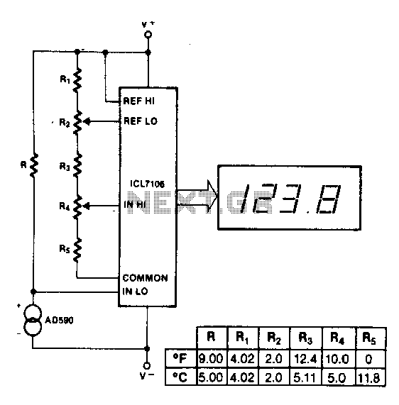
The maximum reading on the Celsius range is 199.9 °C, which is limited by the short-term maximum allowable sensor temperature. The maximum reading on the Fahrenheit range is 199 °F (93 °C), constrained by the number of display digits....
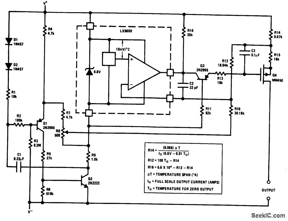
The output of this circuit is a current that is proportional to temperature, which can be utilized to drive a meter for direct readout. Alternatively, a resistor or operational amplifier can be employed to obtain a voltage output. The...
Op-amps have been widely used in low-frequency oscillators. Op-amps, or operational amplifiers, are versatile components frequently utilized in the design of low-frequency oscillators. These devices are capable of generating periodic waveforms, such as sine, square, or triangular waves, which are...
A frequency meter can be utilized in speed sensors, tachometers, or any application that requires the measurement of repetitive signals. This frequency-to-voltage converter (FVC) is designed to facilitate the conversion process. The frequency meter is an essential instrument in various...
This circuit was developed by Luigi Falcone, I1FLC. It utilizes seven plug-in coils that cover a frequency range from 3.0 to 30 MHz within a Colpitts oscillator configuration. A coaxial socket, labeled J2, allows for the connection of a...