
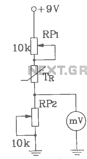
Basic digital thermometer

The electronic circuit described involves a temperature measurement system capable of displaying values in both Celsius and Fahrenheit. The sensor used in this system is designed to operate within specific thermal limits, ensuring accurate readings up to a maximum of 199.9 °C. This limitation is crucial to prevent damage to the sensor and maintain the integrity of the readings.
For the Fahrenheit scale, the system is limited to a maximum reading of 199 °F, which corresponds to approximately 93 °C. This limitation is primarily due to the constraints of the display digits, which may not accommodate higher values effectively without compromising readability.
The reference voltage (Vref) of 500 mV serves as a critical parameter for the analog-to-digital conversion process within the circuit. It establishes a baseline for the sensor's output signal, allowing for precise scaling and conversion of the temperature readings into a digital format that can be displayed. The choice of Vref is essential for ensuring that the entire measurement range is utilized effectively and that the readings are accurate across both temperature scales.
In summary, this temperature measurement circuit is designed with specific operational limits and a defined reference voltage, ensuring reliable and accurate temperature readings in both Celsius and Fahrenheit. The design considerations take into account both the physical limitations of the sensor and the functional constraints of the display system.Maximum reading on the Celsius range is 199,9 °C, limited by the (short-term) maximum allowable sensor temperature. Maximum reading on the Fahrenheit range is 199 °F (93 °C), limited by the number of display digits Vref for both scales is 500 mV.
Related Circuits
T-121 temperature sensor electronic thermometer circuit diagram shown below The T-121 temperature sensor circuit is designed to measure and display temperature readings accurately. The circuit typically consists of a temperature sensor, such as the T-121, which converts temperature variations into...
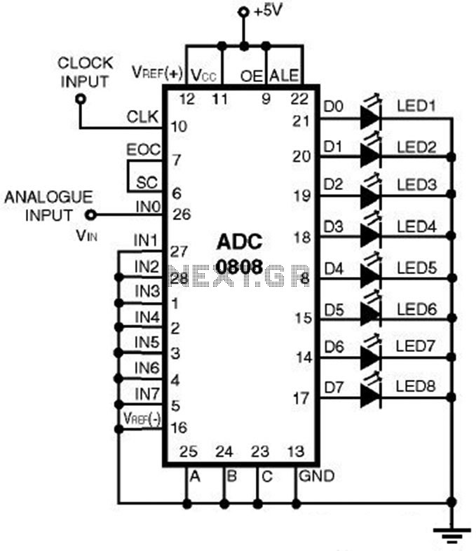
This is a straightforward analog-to-digital converter circuit utilizing an 8-bit analog-to-digital converter (ADC0808). Typically, an analog-to-digital converter (A/D Converter / ADC) necessitates interfacing with a microprocessor to convert analog signals. The ADC0808 is a widely used 8-bit A/D converter that...
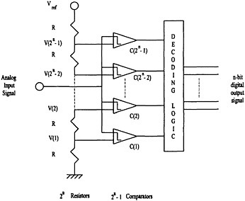
Analog-to-digital converters are categorized into one-step architectures, including flash, folding, and interpolative topologies, as well as multi-step architectures, such as successive approximation and pipeline topologies. The flash architecture is considered the fastest type of analog-to-digital converter due to its...
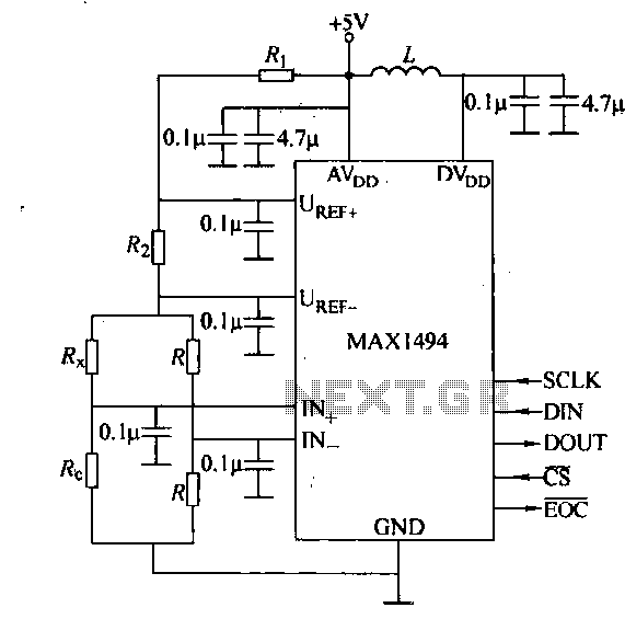
The circuit consists of the MAX1494 digital strain gauge, as illustrated in Figure 5-31. It includes a bridge formed by resistance strain gauges and a temperature compensation sheet. The standard quasi-resistance values Rl and R are incorporated into the...
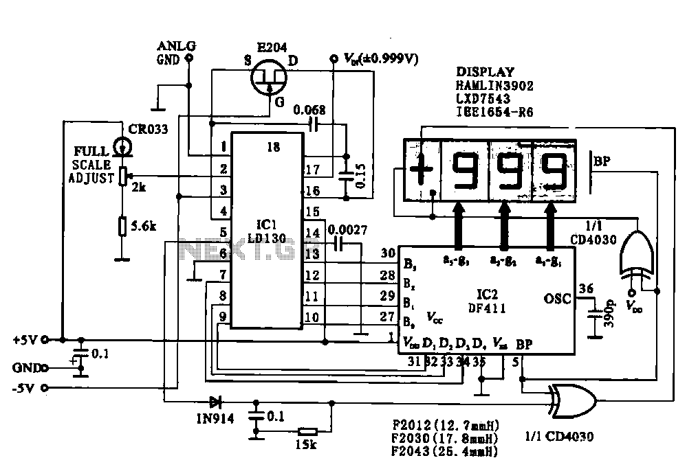
This circuit illustrates a display driving system for a digital voltmeter. The liquid crystal display (LCD) does not emit light by itself; it relies on external incident light for visibility. The integrated circuit (IC) LD130 serves as an input...
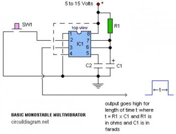
The following circuit illustrates a basic monostable multivibrator, which is based on the 555 Timer IC. Key features include pin 4 functioning as the RESET pin, with the time period defined by the equation t = R1 x C1. The...