
Liquid-Crystal Display (LCD) Tester
 Tester")
The testing circuit described utilizes a square-wave generator, specifically the 4047 integrated circuit, which is designed to produce a symmetrical alternating voltage necessary for testing liquid crystal displays (LCDs). The 4047 operates in astable mode, generating a square wave output with a frequency of approximately 1 kHz. This frequency is suitable for ensuring that the voltage applied to the LCD segments is effective without causing damage. The output from the 4047 goes through a binary scaler, which maintains the symmetry of the waveform, ensuring that there is no direct current component present in the signal.
The power supply for the circuit can range from 3 to 9 volts, typically provided by a battery for portability. However, using a variable power supply allows for fine-tuning of the voltage to determine the optimal operating conditions for the LCD under test. The current drawn by the tester is limited to a maximum of 1 mA, which is safe for the delicate components of the display.
When conducting the test, it is crucial to connect the test voltage between the common terminal (the back plane) and one of the display segments. If the back plane is not readily identifiable, a systematic approach should be taken by connecting one probe to a segment and the other probe to each terminal in succession until the segment is activated and becomes visible. This methodical testing is essential, especially in cases where the LCD may have multiple back plane connections. If a segment does not respond, further investigation into the display's configuration is warranted to locate any additional back plane terminals that may exist. This testing procedure ensures that the integrity of the LCD is maintained while effectively diagnosing any issues with the segments.A segment may be tested by applying an alternating voltage of a few volts across it. Note that the application of a direct voltage will damage the display irreversibly: the resulting current will remove the tracks. The alternating voltage should contain not even a tiny direct voltage component. An alternating current also removes part of the tracks when the current flows in one direction, but restores it when the current flows in the opposite direction. The tester described here consists of a square-wave generator that produces an absolutely symmetrical alternating voltage without any d. c. component. Most logic oscillators are incapable of producing a squarewave signal: they generate rectangular waveforms whose duty cycle hovers around the 50%.
The 4047 used in the tester has a binary scaler at its output that guarantees symmetry. The oscillator frequency is about 1 kHz. It may be powered from a 3 9 V source. Normally, this will be a battery, but a variable power supply has advantages. It shows at which voltage the display works satisfactorily and also that there is a clear relationship between the level of the voltage and the angle at which the display is clearly legible. The tester draws a current not exceeding 1 mA. The test voltage must at all times be connected between the common terminal, that is, the back plane, and one of the segments.
If it is not known which of the terminals is the back plane, connect one probe of the tester to a segment and the other successively to all the other terminals until the segment becomes visible. Note, however, that there are LCDs with more than one back plane. Therefore, if a segment does not become visible, investigate whether the display has a second back plane terminal.
🔗 External reference
Related Circuits
A simple and easy telephone line tester circuit that can be used for testing telephone lines. The telephone line tester circuit is designed to verify the functionality and integrity of telephone lines. It typically comprises a few essential components, including...

A multi-wire cable tester features a separate LED indicator for each wire. It is capable of detecting open circuits, short circuits, reversals, earth faults, and continuity, utilizing four integrated circuits (ICs). Initially designed for intercom systems, it is also...
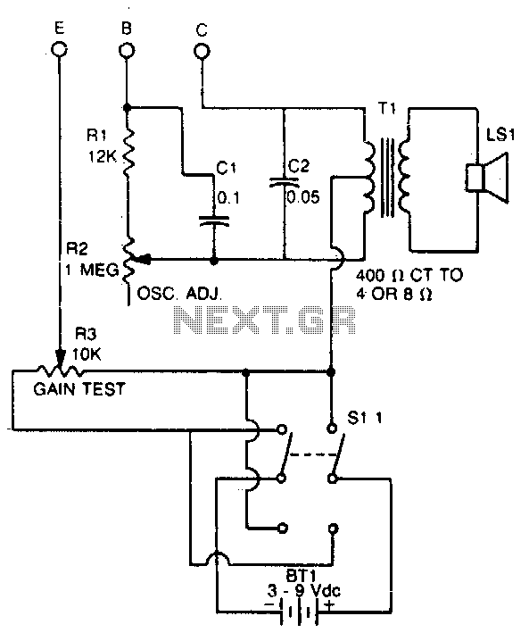
This tester checks the polarity of transistors (PNP or NPN). An audible signal indicates the gain. Additionally, the tester can function as a GO/NO GO tester for matching unmarked devices. The transistor tester is designed to evaluate the polarity and...

When a remote control fails to operate, the issue is often fundamental: the device does not emit light. Possible causes include dry solder joints, faulty LEDs, or a depleted battery, potentially due to a stuck button. The human eye...
This is a simple crystal tester circuit. The transistor T1 and the crystal form an oscillator. Capacitors C1 and C2 act as a voltage divider for the oscillator. If the crystal is functioning properly, the oscillator will operate effectively,...
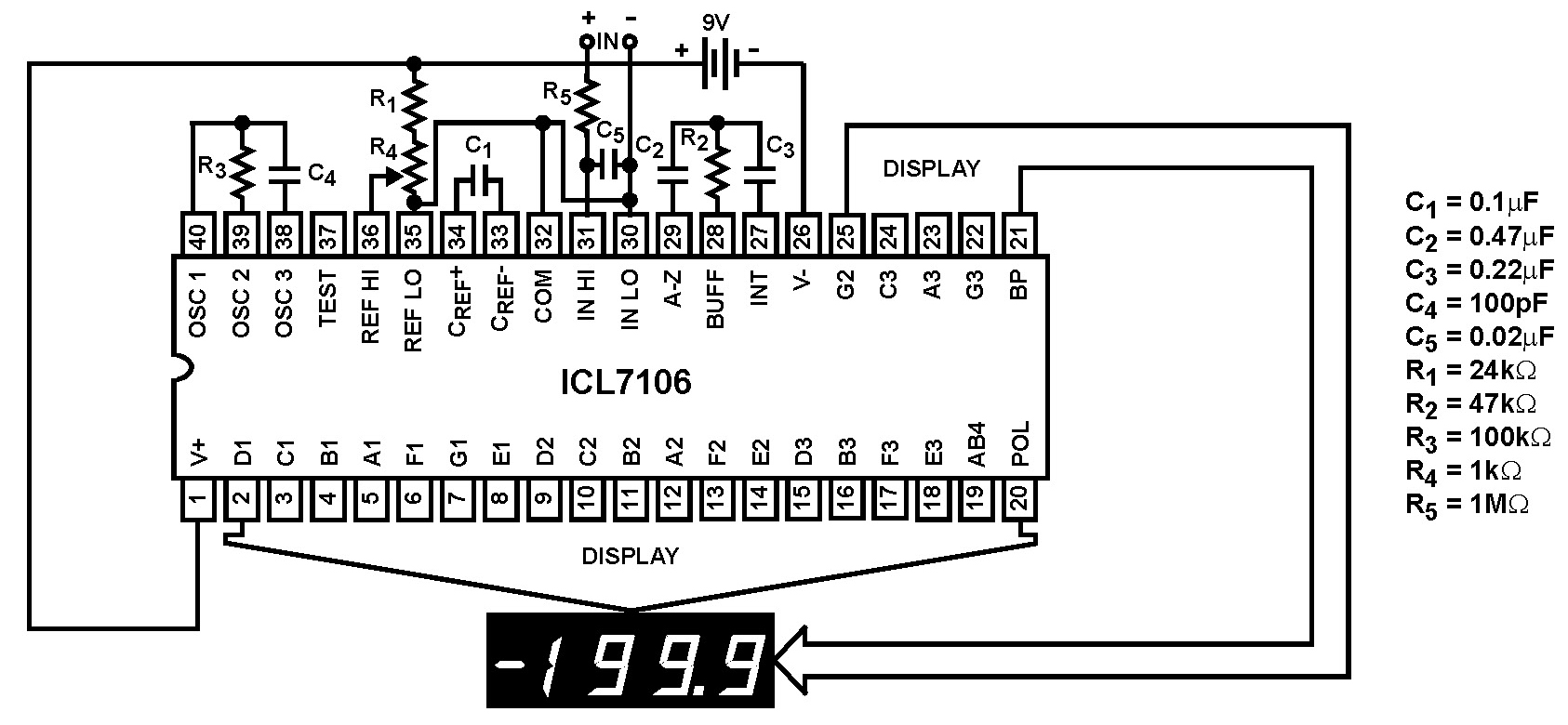
The Intersil ICL7106 and ICL7107 are high-performance, low-power, 3½ digit analog-to-digital (A/D) converters. They include seven-segment decoders, display drivers, a reference, and a clock. The ICL7106 is designed to interface with a liquid crystal display (LCD) and features a...