
Transistor sorter-tester

The transistor tester is designed to evaluate the polarity and gain of bipolar junction transistors (BJTs), which are essential components in various electronic circuits. The primary function of this device is to discern whether a transistor is of the PNP or NPN type. This is achieved through a simple interface that connects the transistor leads to the tester.
Upon connection, the tester applies a small voltage to the transistor and measures the resultant current flow. If the transistor is functioning correctly, an audible signal will be emitted, indicating that the transistor is operational and providing information about its gain, which is crucial for understanding its performance in a circuit.
Furthermore, this tester can serve as a GO/NO GO device. This feature is particularly useful for matching unmarked transistors, which may not have clear labeling for their type or specifications. By providing a straightforward pass/fail indication, the tester simplifies the process of identifying suitable replacements or matching components in circuit design and repair.
The design of the tester typically includes a visual display or LED indicators alongside the audible signal, enhancing usability. The circuit may incorporate a microcontroller or dedicated IC to process the input signals from the transistor and generate the necessary outputs. This ensures accurate readings and reliable performance, making the tester an invaluable tool for electronics engineers and hobbyists alike.This tester checks transistor for polarity (PNP or NPN). An audible signal will give an indication of gain Tester can also be used as a GO/NO GO tester to match unmarked devices.
Related Circuits

Each bistable circuit comprises two oppositely-symmetrical germanium transistors, two diodes, and four resistors. An additional transistor, Q, facilitates the transition of the conducting state to the next position when actuated by a transfer pulse. The absence of capacitors allows...
This is a transistor inverter circuit diagram rated for 100 watts, designed as an easy-to-build circuit. It utilizes only transistors and does not incorporate any integrated circuits. The circuit converts a 12V battery input to a 220V, 50Hz square...
The following circuit illustrates a Power Amplifier Circuit Diagram utilizing a 2N3055 transistor. Features include a 500-ohm current and an optimal voltage of 50V. The power amplifier circuit based on the 2N3055 transistor is designed to deliver significant output power,...
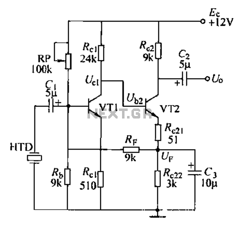
Dctl is a two-stage amplifier, with the first stage amplifying the collector voltage of transistor VT1. The second stage, represented by VT2, is proportional to the current flowing through the winding. The RF signal is applied to the sub-base...
The 2N2222 circuitry is a three-element phase-shift oscillator circuit designed to produce a 1,000 Hz sine wave. This sine wave is subsequently applied to the TCG-610 varactor diode, which has a capacitance of 6 pF at 4 V. The...
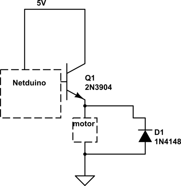
When the motor is connected in this manner, the Netduino activates the transistor, but nothing occurs. Swapping the motor with an LED results in the LED lighting up, indicating that the motor is not receiving sufficient power. Connecting the...