
Lithium-Polymer Peak Charger

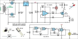
The charging circuit for Lithium-Polymer cells is constructed around a voltage regulator (REG1) and incorporates a current-limiting transistor (Q2) to ensure safe and efficient charging. The design supports two 800mAh cells connected in series, which allows for a total nominal voltage of 7.4V (3.7V per cell). The charging process begins with the activation of switch S1, which closes the relay contacts, thereby connecting the battery pack to the voltage regulator's output.
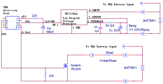
The constant-current, constant-voltage charging method is crucial for Lithium-Polymer cells. Initially, the circuit provides a constant current of 600mA to the cells. As the battery voltage rises, the charging current is monitored through resistor R7. When the current exceeds the threshold, Q2 is activated, which adjusts the output voltage of REG1 downward to maintain the charging current at 600mA. This prevents the cells from being overcharged, which can lead to thermal runaway or cell damage.
As the cells approach their peak voltage of 4.2V, the charging current begins to taper off, indicating that the cells are nearing full charge. This gradual decrease in current is essential for maintaining the health and longevity of Lithium-Polymer batteries. The monitoring of the voltage across R7 ensures that the system can effectively terminate the charging process when the cells are fully charged.
The relay mechanism, controlled by transistor Q1, plays a critical role in isolating the battery once charging is complete. The circuit design ensures that no current flows to the battery when it is fully charged, thus preventing overcharging. An ammeter is included in the circuit to provide real-time feedback on the charging current, allowing for monitoring of the charging process.
Overall, this circuit design provides a robust solution for charging Lithium-Polymer cells in model aircraft, ensuring safety, efficiency, and longevity of the battery pack.This circuit was developed to charge the Lithium-Polymer cells used in a model aircraft. Lithium-Polymer cells are incredibly lightweight compared to Ni-cad battery packs of the same voltage and amp-hour rating. Their only drawback is that they require a rigid charge and discharge regime to achieve maximum life.
The most important points of note a re as follows: They should be charged using a constant-current, constant-voltage method, which stops the charge once the current has dropped to about the C/10 rate. For example, for an 800mAh pack, charging should be terminated once the current falls to approximately 80mA.
To initiate charging, the momentary "Start" button (switch S1) is pressed, closing the relay contacts and connecting the battery pack to the output of REG1. The circuit will then charge two 800mAh cells in series at a constant current of 600mAh until they reach a peak terminal voltage of 4.
2V per cell (nominal terminal voltage for these cells is 3. 7V). REG1 and transistor Q2 form a current-limited voltage regulator. When the charge current exceeds about 600mA, the voltage developed across R7 turns on Q2, which in turn pulls the adjust terminal of REG1 towards ground. This shunts the voltage adjustment resistance chain formed by VR2 and R3, thereby limiting the output to 600mA.
When the battery voltage reaches about 8. 4V, the regulator limits any further voltage increase, as set by VR2. The charge current will then slowly decrease as the cells reach full capacity. As a result, the voltage across R7 also falls, until the bias voltage on the base of Q1 is too small to keep it in conduction. When Q1 turns off, the relay also turns off, isolating the fully charged battery. Place an ammeter in series with the battery to be charged and press the "Start" button. The output current will shoot up to around 600mA, then slowly decrease over the next one to two hours.
🔗 External reference
Related Circuits
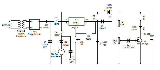
Battery charger utilizing solar and electrical power with a circuit diagram. This dual power source battery charger can charge a lead-acid battery using two different power sources. The battery charger circuit is designed to efficiently charge a lead-acid battery by...
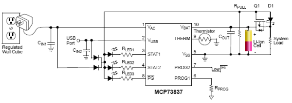
Designing a Li-Ion Battery Charger with Load Sharing MCP73837. Batteries frequently serve as the primary energy source for portable electronic devices. Although these devices rely on batteries, portable consumer electronics such as GPS devices and multimedia players often draw...
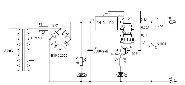
Charger for all battery types power supply. This lithium battery charger circuit is dedicated to charging lithium batteries. It uses two chips: the voltage regulator LM317T and ICL7665, which warns microprocessors of overvoltage and undervoltage conditions. Charging is completed...
This circuit charges two NiCad cells with a constant current and features dual charging rates, voltage cutoff, and an audible alarm. The circuit is powered. This circuit is designed to efficiently charge two nickel-cadmium (NiCad) cells, utilizing a constant current...
The UBA is limited to discharging up to 2.5A per channel. This discharge rate is adequate for testing 99% of the batteries on the market. However, it is insufficient for properly testing batteries that are rapidly discharged in normal...
The circuit is designed for charging NiMH batteries using the MAX712 integrated circuit (IC), which provides all necessary functionalities for controlled charging. The schematic of the charger is centered around IC1, the MAX712 from Maxim, which comes in a...