
NiMH Charger For Up To Six Cells

The circuit operates on the principle of constant voltage and current regulation, ensuring that the NiMH batteries are charged safely and effectively. The MAX712 IC incorporates features such as automatic termination of charging when the cells reach full capacity, which is critical for preventing overcharging and prolonging battery life. The selection of R1 is crucial as it directly influences the charging current; thus, careful consideration must be given to its value based on desired charging rates.
The use of dongles to set parameters enhances the flexibility and adaptability of the charging circuit, allowing it to accommodate various battery configurations and capacities. The connectors K3 and K4 serve as user-friendly interfaces for easy adjustments without the need for extensive modifications to the circuit board.
Thermal management is also a key consideration in this design. The transistor T1, responsible for current regulation, may generate heat during operation, especially under high load conditions. Therefore, a heatsink may be necessary to maintain safe operating temperatures and ensure reliability.
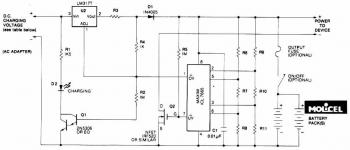
In conclusion, this charging circuit exemplifies a robust design for hobbyists and professionals alike, combining ease of use with effective battery management, making it suitable for a range of NiMH battery applications. The potential for modification with different ICs further enhances its versatility, allowing for adaptation to other battery chemistries, such as NiCd, while maintaining efficiency and safety.The circuit presented here is intended for charging NiMH batteries. The MAX712 IC used here contains all the necessary functionality to make sure that this happens in a controlled manner. Figure 1 shows the schematic of the charger. The heart of the circuit is easily recognized: everything is arranged around IC1, a MAX712 from Maxim.
This IC is available in a standard DIP package, which is convenient for the hobbyist because it can be directly fitted on standard though-hole prototyping board. IC1 uses T1 to regulate the current in the battery. R1 is used by IC1 to measure the current. While charging, IC1 attempts to maintain a constant voltage, equal to 250 mV, across R1. By adjusting the value of R1 the charging current can be set. The value of R1 can be calculated using the formula below: R1 = 250 mV / I charge For a charging current of 1 A, the value of R1 has to be 250 mV / 1 A = 0. 25 ©. The power dissipated by R1 equals U G— I = 0. 25 G— 1= 250 mW. A 0. 5-watt resistor will therefore suffice for R1. Transistor T1 may need a small heatsink depending on the charging current and supply voltage. IC1 needs a small amount of user input regarding the maximum charging time and the number of cells in the battery to be charged.
IC1 has four inputs, PGM0 to PGM3, for this purpose. These are not ordinary digital inputs (which recognise only 2 states) but special inputs that recognise 4 different states, namely V+, Vref, BATT or not connected. To make this a little bit more user friendly, we`ve brought out the necessary connections to 2 connectors (K3 and K4).
A number of dongles have been made (Figure 2) that can be plugged into these connectors and set the number of cells and the maximum charging time. When determining the maximum charging time we have to take into account the charging current and the capacity of the cells that are connected.
The charging time can be calculated with the formula: Tcharge = Ccell / I charge G— 1. 2 where Ccell is the capacity in Ah (e. g. , 1200 mAh = 1. 2 Ah). After the nominal charging time has been calculated, we can use the first dongle that has a value that is equal or greater than the calculated charging time. For example, if we calculated a maximum charging time of 38 minutes, we have to select the dongle for 45 minutes.
When IC1 is replaced by a MAX713, the charger becomes suitable for charging NiCd batteries (but not suitable for NiMH batteries any more!). The only difference between these two ICs is the value of the detection point at which the cell(s) are considered to be comple
🔗 External reference
Related Circuits
Schematic and description of a simple and easy-to-build NiCd and NiMH battery charger circuit that is capable of charging multiple NiCd and NiMH batteries. The circuit for the NiCd and NiMH battery charger is designed to be straightforward, allowing for...
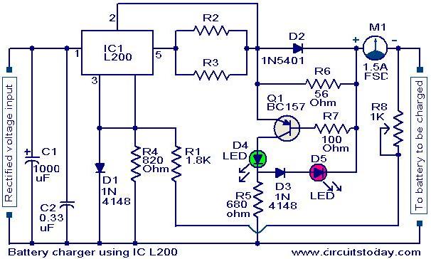
A simple battery charger circuit with reverse polarity indication is presented here. The circuit utilizes the L200 integrated circuit (IC), which is a five-pin variable voltage regulator. The charging circuit can be powered by DC voltage from either a...
Lithium Ion batteries pack a lot of power by weight compared to other types. There are 2 things that need to be handled differently than nicad or NiMH. They cannot be used as a direct substitute (even if they...
This circuit illustrates a Lithium Battery Charger circuit diagram. Charging is achieved using a constant current of 60 mA for AA cells until a cutoff voltage of 2.4V per cell is reached, at which point the charging process must...
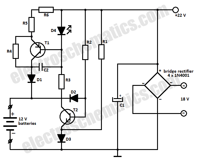
This battery charger circuit is designed to charge one or more batteries with a total nominal voltage of 12 V, which accommodates either ten NiCd batteries or six 2 V lead-acid batteries. The battery charger circuit operates by utilizing a...
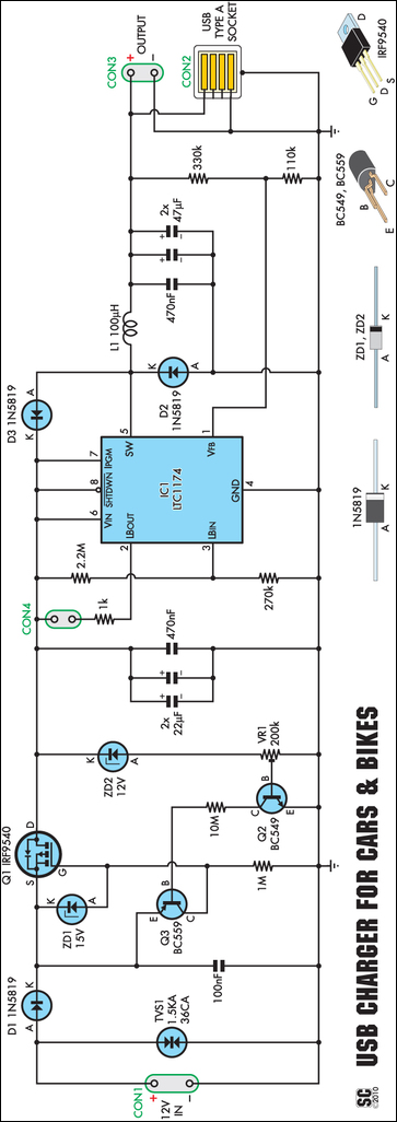
A regular charger was tested and found to consume 13mA with no load. It features an integrated power LED, which significantly contributes to standby current consumption. However, since the cigarette lighter socket is powered only when the engine is...