
Little dipper

The circuit is designed to operate effectively across a frequency range from Low Frequency (LF) to Very High Frequency (VHF), provided that suitable components are selected.
The oscillator section utilizes a Colpitts configuration, which is characterized by its use of a capacitive voltage divider to create feedback for the oscillation process. In this setup, the FET serves as the active device, amplifying the oscillations generated by the tank circuit. The tank circuit typically consists of an inductor and two capacitors, which determine the oscillation frequency. The precise values of these components can be adjusted to achieve the desired frequency response.
Capacitor C4 plays a crucial role in coupling the output of the oscillator to the detector circuit. This coupling allows for the transfer of the oscillation energy without significantly loading the oscillator, ensuring stable operation. The detector circuit, featuring diode D2, functions as a rectifier, converting the AC signal produced by the oscillator into a DC voltage. This rectified voltage is essential for driving the subsequent amplification stage.
The Darlington pair configuration, comprising transistors Q2 and A3, is utilized to provide high current gain, which is beneficial for driving the LED indicator. The sensitivity control resistor (R3) allows for adjustment of the amplifier's bias point, enabling fine-tuning of the circuit's response to incoming signals. This feature is particularly useful in applications where signal strength may vary.
The LED indicator serves as a visual output, providing feedback on the circuit's operation. In DIP mode, the LED's brightness corresponds directly to the current flowing through it, which varies with the input signal's amplitude. In contrast, the PEAK mode alters the response by introducing a voltage drop across resistor R5, which inversely affects the LED's operation, providing a different visual indication of the signal's characteristics.
Overall, this circuit design is versatile and can be adapted for various applications within the LF to VHF range by selecting appropriate components that match the desired operational frequency and performance specifications.The circuit consists of two basic circuits, the oscillator and the detector. The oscillator uses an FET in a Colpitts configuration. The energy circulating in the oscillator tank is coupled through C4 to the detector circuit, where a small diode (D2) rectifies it, feeding a dc voltage to the Darlington pair (Q2, A3) controlled by the sensitivity control (R3). Any small variations in the bias of the amplifier will cause large variations of current through the LED indicator in the DIP mode; however, ih the PEAK mode the current produces a corresponding voltage drop through R5 and the action of the LED is reversed.
The circuit shown will work practically on any frequency from LF to VHF if the appropriate components are used.
Related Circuits
The measuring resonant circuit, while actively operating, is loosely coupled to the resonant circuit of the dipper, meaning it is brought close to it. The dipper is tuned from the lowest to the highest frequency. When the dipper and...
If a complete circuit is needed, there are thousands of these circuits available in the designs. Some of them can be provided easily, but further communication is required. The request indicates a need for a comprehensive circuit design, which may...
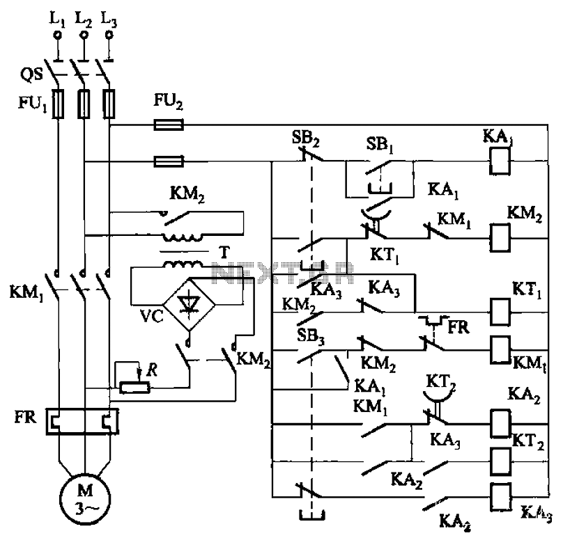
The circuit depicted in Figure 3-143 demonstrates a braking mechanism for a motor that operates effectively during normal shutdown and jog operations. The circuit includes several components, such as the start button (SBz), stop button (SBz), and jog button...
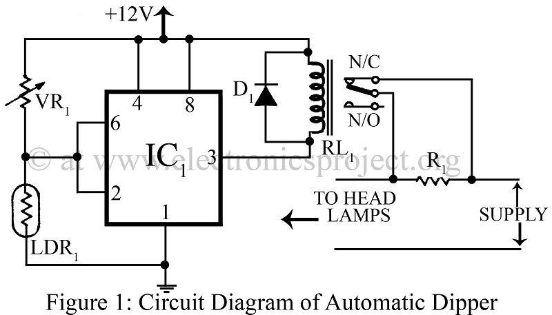
An automatic dipper for vehicles utilizing a timer IC NE555 and a light-dependent resistor (LDR) to control the headlight intensity of vehicles. This circuit diagram serves as a reference for various automobile projects. The automatic dipper circuit employs the NE555...
This is a compact collection of amplifiers configured in a bridge connection. The output power is low, making them suitable for general applications. They can be utilized with small active loudspeakers, car stereos, and similar devices. The only limitation...
This glowing Halloween ghost is available as a kit from the Tuxgraphics online shop. It can emit a friendly glow or produce scary flashes. Users can choose their own facial design to create either a friendly ghost or a...