
Automatic Dipper for Vehicles using NE555

The automatic dipper circuit employs the NE555 timer IC configured in an astable mode to generate a pulse-width modulation (PWM) signal, which is instrumental in controlling the headlight intensity based on ambient light conditions. The LDR is used as a sensor to detect the level of surrounding light. When the ambient light falls below a certain threshold, the resistance of the LDR decreases, triggering the NE555 timer to activate the vehicle's headlights at a lower intensity.
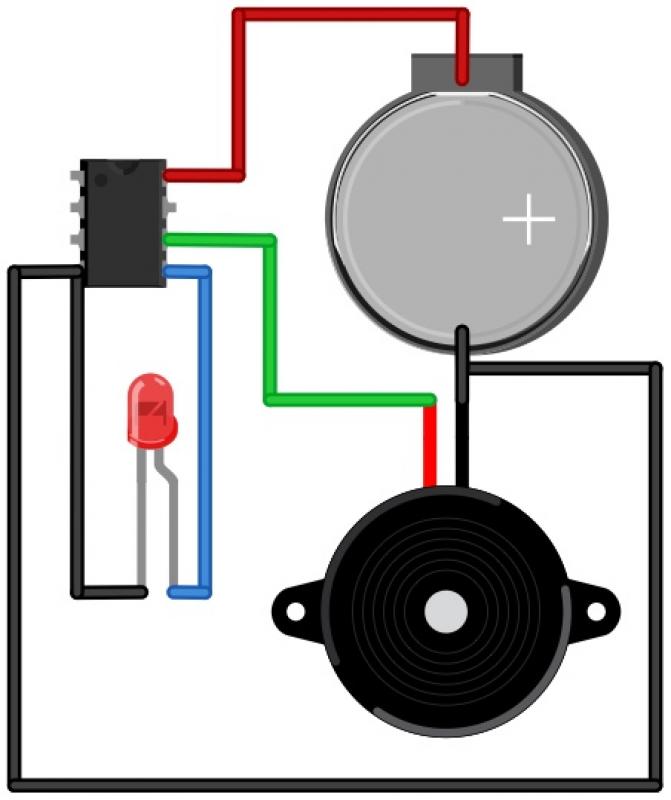
The circuit typically includes a few key components: the NE555 timer, the LDR, resistors, capacitors, and a relay. The relay serves to switch the vehicle's headlights on and off or change their intensity based on the output from the NE555 timer.
In operation, the LDR continuously monitors the light levels. When it senses low light, the NE555 timer is activated, and the output pin of the timer sends a signal to the relay. The relay then engages, allowing current to flow to the headlights and dimming them as necessary. The timing components (resistors and capacitors) connected to the NE555 determine the sensitivity and response time of the circuit, allowing for customization based on the specific requirements of different vehicles.
This automatic dipper circuit enhances driving safety by ensuring that headlights are appropriately adjusted according to environmental conditions, thus preventing glare to oncoming drivers and improving visibility for the vehicle's operator.Automatic Dipper for Vehicles using timer IC NE555 and LDR use to dip the light of vehicles circuit diagram with description various automobile project. 🔗 External reference
Related Circuits

A simple circuit diagram illustrates a schematic for a remote control system, which consists of two components: a transmitter and a receiver. The transmitter circuit is controlled by the NE555 integrated circuit (IC). This system operates by detecting the...
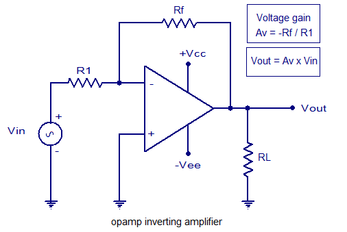
An inverting amplifier utilizing an operational amplifier (op-amp). This includes equations for voltage gain and output voltage, as well as input and output waveforms, and a practical inverting amplifier circuit using the 741 IC. An inverting amplifier is a fundamental...
This article describes a 2-Input alarm developed on the PIC LICK-1 Module using a Microchip PIC16F628-04. The program uses the internal 4MHz oscillator and if any other frequency is used, the timer values will need to be changed. A...
The automatic sprinkler controller circuit consists of a power supply circuit and a humidity measurement and control circuit, as illustrated in the accompanying figure. The power supply circuit includes a power transformer (T), rectifier diodes (VD1 to VD4), filter...
This metal detector schematic circuit is based on a transistor radio as a detector. This metal detector is entirely different from other metal detectors because this circuit does not have a speaker. With the radio tuned to a weak...
The Morse Beepy is a circuit designed to be simple and affordable, making it suitable for both children and adults as an introductory soldering project. It can be assembled and programmed within fifteen minutes to beep and blink a...