
lm 3915 vu meter

The described circuit is a visual audio level indicator utilizing the LM3915 LED display driver, which can be configured for various applications, including audio signal monitoring. The LM3915 operates by lighting up a series of LEDs proportionally to the input voltage level, providing a visual representation of the signal strength. The addition of a peak detector circuit is essential for accurately capturing transient peaks in audio signals, ensuring that the LEDs illuminate brightly enough to be noticed during brief signal spikes.
In this implementation, the choice of components plays a crucial role in performance. The 68-ohm resistor serves to limit the current flowing through the LEDs, protecting them from excessive current that could lead to failure. The substitution of the 2.7k resistor with a 1.2k resistor alters the sensitivity of the circuit, allowing for a more responsive display that better reflects audio signal dynamics.
The passive peak detector's limitation in detecting low signal levels below 0.6V is a significant consideration for audio applications where low-level signals are common. A more effective solution may involve an active peak detection circuit, which could provide better performance across a wider range of input signal amplitudes.
The use of a 10k potentiometer allows for fine-tuning of the circuit's sensitivity, which is particularly beneficial in environments with varying signal strengths. This feature helps to prevent the LEDs from constantly peaking, which can lead to unnecessary power consumption and reduce battery life.
In summary, this schematic provides a basic yet functional design for an audio VU meter, leveraging the LM3915 and a peak detector circuit. Careful component selection and configuration are essential for optimal performance, particularly in maintaining the integrity of low-level signals while ensuring the circuit remains compact and efficient.* This meter looked like it works well: YouTube - IndikG tor vybuzenG s LM3915 but the schematic is quite different. Google Translate If I followed that schematic, do you think everything would still work You should use a peak detector circuit at the input so that momentary peak voltages light the LEDs long enough to appear bright, instead of th
e dim blur or not seen. I made one myself not too long ago using the LM3915, not my schematic, but i use it and not pictured, i added a 68 © 1/2w resistor between the anode end of the LEDs and the positive power source. I also substituted the shown 2. 7k resistor for a 1. 2k resistor. For demo purposes due to the size limitation of the PCB, i used 3mm LEDs, hooked up for single channel, runs off a +9v battery and i incorporated an off/on switch.
The passive peak detector using a diode ruins the low signal levels that have a voltage less than 0. 6V peak so the circuit does not show the low signal levels. The passive peak detector using a diode ruins the low signal levels that have a voltage less than 0. 6V peak so the circuit does not show the low signal levels Unfortunately true. but i wanted to use as little parts/space as possible due to the size of the PCB i used and it works well for me. For the moment, my circuit is hooked up to the "lineout" of the sound card and to get more than enough signal strength, i max the sound in windows.
With the 10k pot, i can always adjust the sensitivity to the IC so the LEDs are not peaking half the time causing a quicker battery drain. I use amplified stereo speakers that has volume control so it doesnt matter and i prefer using the preamped output because the vu meter still displays no matter what volume level on the speakers.
I may be wrong but im sure this circuit was more designed towards hooking up directly to speakers wheres theres more peak power to overcome the 0. 6v drop of the diodes. Yeah. the peak detector circuit doesn`t work. The one with the transistor, not the other one. Just causes the chip to get super hot and light up most of the LEDs. I could`ve set it up wrong, but I triple checked. The transistor peak detector circuit works perfectly if the transistor and diode are not connected backwards.
If the wrong diode is used (a 1N400x rectifier) then a few LEDs might light without an input signal. A 1N4148 diode is the same as a 1N914 diode. 🔗 External reference
Related Circuits
In general, the transceiver switches the 4-element 1500 ohm xtal BPF ends between the inputs and outputs of the two SA602s to reverse the signal flow for R/T operation. Since no IF amplifier is used in the design, 20...
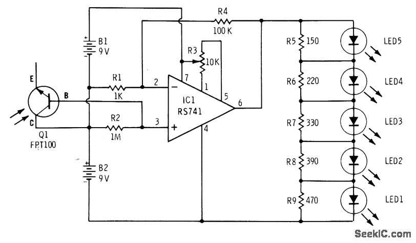
The phototransistor Q1 (Radio Shack 276-130) activates a voltage change across resistor R2, which is then amplified by an operational amplifier (op-amp). The output from the op-amp drives an array of five LEDs, creating a bar graph voltage indicator....
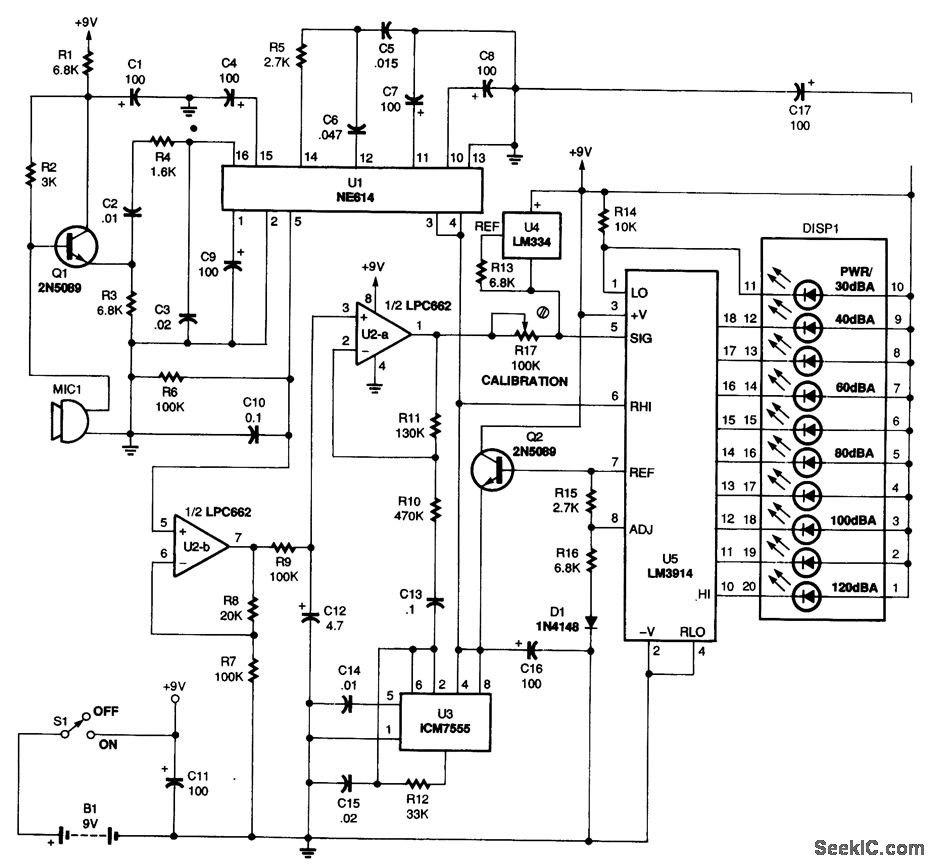
Power for the circuit is supplied by a 9-V battery (B1), providing a total current of 14.5 mA, which allows an alkaline battery to last approximately 250 hours. Audio signals are captured by the microphone (MIC1), and the output...
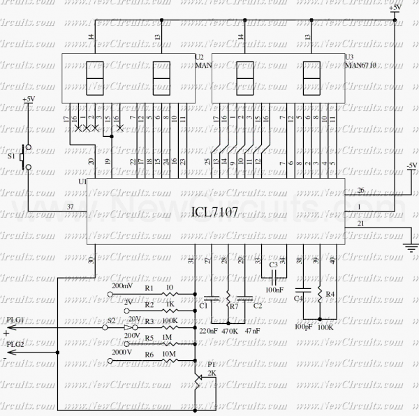
The ICL7107 is a 3 1/2 digit LED A/D converter. It contains an internal voltage reference, high isolation analog switches, sequential control logic, and the display drivers. The auto-zero adjust ensures zero reading for 0 volts input. The ICL7107 is...
This is a 7-digit frequency meter measuring frequency from 10 Hz up to 1300 MHz. It is based on ideas of PIC16F84 based frequency meter. The measuring range is divided into two subranges: 10Hz - 25MHz and 25 MHz...
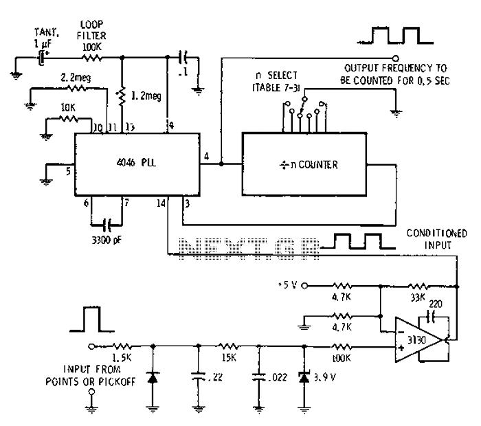
Automotive engine pulse points or other sensors are filtered using the transmission device 3130 CMOS operational amplifier, which functions as a comparator to fulfill the input conditions. The pulse subsequently flows into a 4046 phase-locked loop (PLL) N-counter, which...