
LIGHT METER WITH LED READOUT

The circuit design incorporates a phototransistor (Q1), which serves as the primary light sensor. When illuminated, Q1 generates a current that flows through resistor R2. This current induces a voltage drop across R2, which is proportional to the intensity of the incident light. The voltage change across R2 is fed into the non-inverting input of the operational amplifier, which amplifies the signal. The gain of the op-amp can be configured by selecting appropriate resistor values in the feedback loop.
Resistor R3 plays a critical role in calibrating the circuit's sensitivity. By adjusting R3, the threshold at which the first LED lights up can be finely tuned. This adjustment ensures that LED 1 only turns on when ambient light levels are sufficiently low, allowing for precise control over the activation of the LED array as light levels change.
The five LEDs are connected to the output of the op-amp, arranged in a manner that allows them to light up in sequence. This arrangement provides a visual representation of the light intensity detected by the phototransistor. The circuit is designed to ensure that each LED remains lit once it has been activated, creating a clear and intuitive bar graph display.
In addition to the phototransistor, the circuit can accommodate alternative light sensors, such as solar cells or selenium cells. These alternatives may offer different sensitivity characteristics or response times, allowing for flexibility in application depending on the specific requirements of the project.
This electronic schematic is particularly useful in applications requiring visual feedback based on light levels, such as ambient light monitoring, light-sensitive alarms, or educational demonstrations of photonic principles. The simplicity of the design allows for easy replication and modification, making it a valuable project for both novice and experienced electronics enthusiasts.Light onphototransistorQ1 (Radio Shack 276-130) produces voltage change across R2 for amplification by opamp whose output drives array fiveLEDs forming bar graph voltage indicator. Adjust R3 initially for highest sensitivity by tuming off room lights and rotating until LED 1 just stops glowing.
Now, as light is gradually increased on sensor, LEDs come on one by one in upward sequence and stay on until all five are lit. Solar cells or selenium cells can be used in place of phototransistor. -F. M. Mims, "Opto-electronic Projects, Vol. 1, " Radio Shack, Fort Worth, TX, 1977, 2nd Ed. , p 85-93. 🔗 External reference
Related Circuits
The circuit utilizes a quad voltage comparator (LM339) as a basic bar graph meter to display the charge status of a 12-volt lead-acid battery. A 5-volt reference voltage is applied to each of the positive (+) inputs of the...

This circuit demonstrates the utilization of a standard LED as a light sensor. It leverages the photovoltaic voltage generated across the LED when exposed to light. The circuit operates on the principle that an LED can function as a photodiode,...
Create LED lighting powered directly from the AC mains (120-Volt AC) due to the unavailability of inexpensive and safe enclosures for the circuitry. While collecting old failed CFLs for recycling, it was noted that the body of CFLs (also...

A phototransistor detects daylight. At dusk, it stops conducting, and Rl biases Q2, activating Kl, which turns on the light. At dawn, Ql begins to conduct, cutting off Q2. Kl deactivates, and the light turns off. The circuit utilizes a...
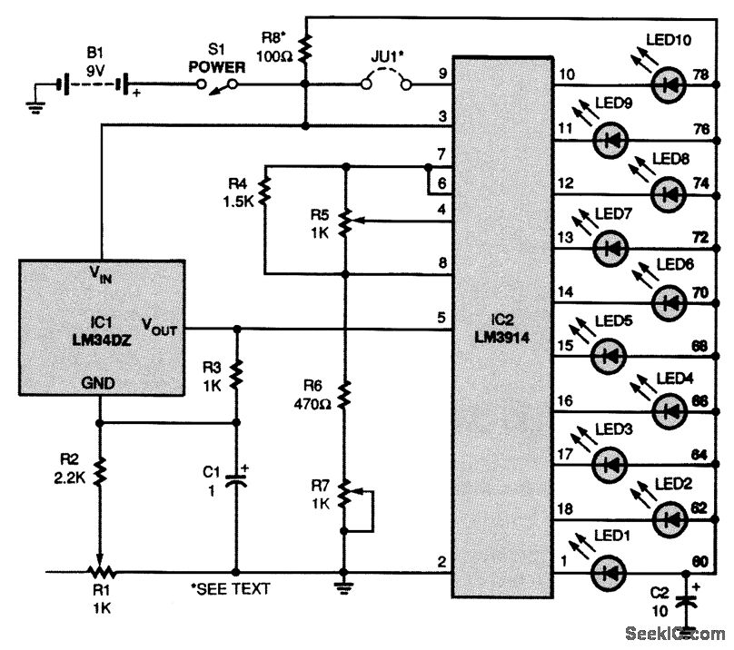
The circuit is powered by a 9-V battery (B1) but can also operate with any 7- to 10-V DC power supply. At the core of the thermometer is IC1, an LM34 temperature sensor, which generates a voltage between the...

4017 LED Knight Rider Running Light Circuit Diagram. In this 4017 Knight Rider circuit, the 555 timer is configured as an oscillator. It can be adjusted to produce a variety of timing intervals. The 4017 LED Knight Rider circuit utilizes...