
LM1877 amplifier having a control circuit diagram of the bass

The circuit utilizes the LM1877 integrated circuit, which is designed for audio amplification applications, particularly in bass-heavy environments. The configuration allows for effective manipulation of audio signals, ensuring that both the left and right channels are balanced and provide a rich sound output. The use of cermet potentiometers is advantageous due to their stability and longevity, making them suitable for audio applications where precision is critical.
In this setup, the two 1M potentiometers not only control the volume but also help in maintaining the integrity of the audio signal by minimizing distortion. The coupling capacitors of 0.1 µF act as high-pass filters, eliminating unwanted low-frequency noise that could interfere with the audio clarity. The feedback loop involving the 100k potentiometers is crucial for fine-tuning the bass response, allowing the user to adjust the tonal quality of the sound output to their preference.
The addition of 2.7 ohm resistors in parallel with the speakers serves to dampen any high-frequency oscillations that may arise, enhancing the overall sound quality by providing a smoother response. The capacitors in this configuration act as bypass elements, ensuring that high-frequency noise is filtered out before reaching the speakers, resulting in a cleaner sound reproduction.
Overall, this circuit design effectively combines various components to create a robust bass amplification system suitable for performance settings, where sound quality and control are of utmost importance. Bass player with a stereo control as shown by LM1877 amplifier circuit configured. Cermet stereo microphone pickup stereo turntable on the left and right channel audio signals through two 1M potentiometer input, respectively, by two 0.1 F capacitive coupling is applied to the input of LM1877 6,9 feet, amplified by two, 13 feet respectively output, respectively, to the left and right channel speaker. Among them, two 1M potentiometer for the volume potentiometer, two potentiometers linkage for adjusting the volume.
1 and connected to two feet 1M resistor is used to set the amplifier operating point of DC bias, and coupling capacitors and 0.1 F input high-pass filter. Connected in a feedback loop between the amplifier 2 feet and 7 feet 100k potentiometer (Similarly, connected between the amplifier 13 feet and 8 feet feedback loop 100k potentiometer) for the bass control potentiometer.
Respectively, of the left and right channel loudspeaker parallel 2.7 resistor, 0.1 F capacitor for filtering high frequency noise.
Related Circuits
High-quality audio amplifier for computer circuit diagram. The electrical circuit of the amplifier is depicted in Fig. 1. The chosen integrated circuit for its construction is the TA8205AN, which is typically used in Hi-Fi applications due to its low...
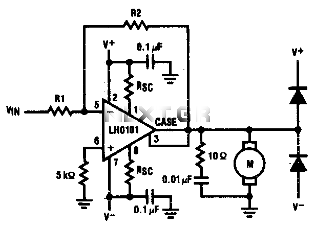
The motor driver amplifier is designed to deliver the rated current to the motor. It is important to manage power dissipation to remain within allowable limits. This precision speed regulation circuit utilizes rate feedback to maintain a constant motor...
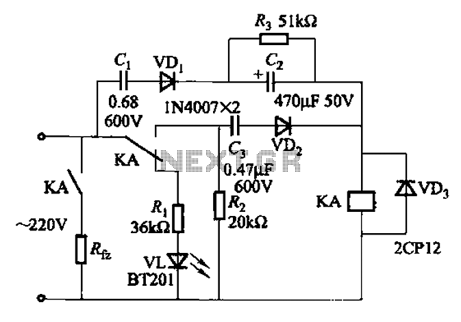
The AC power supply voltage is normal, and a relay is connected to the load (Rfz) circuit. In the event of a load short-circuit failure, the voltage across relay KA drops rapidly, causing KA to release and disconnect the...
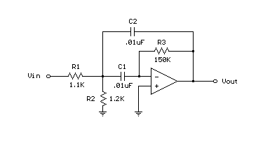
A bandpass filter allows a specific range of frequencies to pass while rejecting frequencies that fall outside the upper and lower limits of the passband. The frequencies that are permitted to pass are referred to as the passband, which...
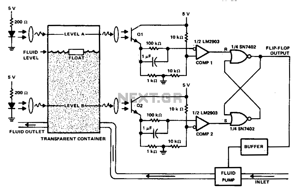
This circuit can be used to maintain fluid between two levels. Variations on this control circuit can be made to keep something that moves within certain boundary conditions. The described circuit functions primarily as a fluid level control system, designed...
The yellow wires on the far right serve as temporary power connections, allowing battery power to enter through the contact studs located in the large holes that press against the radio's battery terminals. The cable in the lower right...