
LM2576T IC Step-Down Switching Power Supply

The LM2576T is a popular voltage regulator known for its ability to efficiently convert a higher input voltage to a lower output voltage, making it suitable for various applications requiring power regulation. The circuit typically comprises an LM2576T IC, which is designed to handle input voltages up to 60V and can deliver a maximum output current of 3A.
The schematic includes several key components:
1. **Input Capacitor (C1)**: This capacitor filters the input voltage and stabilizes it before it reaches the LM2576T. A value of 100µF is commonly used to ensure adequate filtering, which helps to reduce voltage spikes that could damage the IC.
2. **Inductor (L1)**: The inductor is crucial for energy storage in the switching process. It allows the circuit to maintain a steady output voltage by storing energy when the switch is closed and releasing it when the switch is open. The inductance value is typically in the range of 33µH to 100µH, depending on the desired output voltage and current.
3. **Diode (D1)**: A Schottky diode is often employed in this circuit configuration due to its fast switching capability and low forward voltage drop. This diode is positioned in parallel with the load and is essential for allowing current to flow back to the output when the inductor discharges.
4. **Output Capacitor (C2)**: This capacitor smooths out the output voltage and reduces ripple. A value of 220µF is commonly used to ensure that the output remains stable under varying load conditions.
5. **Feedback Resistors (R1 and R2)**: These resistors form a voltage divider that provides feedback to the LM2576T, allowing it to regulate the output voltage accurately. The resistor values can be selected based on the desired output voltage.
6. **Additional Components**: Depending on the application, additional capacitors and resistors may be included to further stabilize the circuit and improve transient response.
This configuration is versatile, allowing for adjustments to meet specific voltage requirements. The LM2576T's built-in thermal shutdown and current limiting features enhance the circuit's reliability, making it suitable for a wide range of electronic devices and systems.This circuit shows about LM2576T IC Step-Down Switching Power Supply Circuit Diagram. Features:60V input voltage, 3.3 V/5V/12V/15V output .. 🔗 External reference
Related Circuits
The circuit is built around two 555 timer ICs, U1 and U2. U1 is configured as a variable duty cycle oscillator with a constant time period of approximately 0.1 seconds. The duty cycle can be adjusted from 0 to...
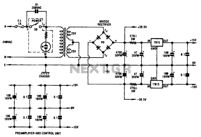
A dual audio amplifier that delivers 50 W per channel is illustrated in the schematic. It features a preamplifier and tone controls, as well as a headphone amplifier. The circuit also shows a power supply providing 38.5 V and...
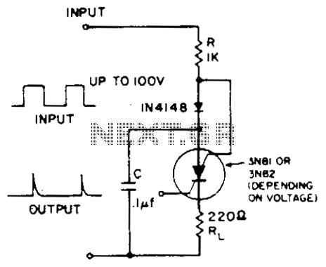
A positive-going input charges capacitor C through the IN4148 diode and resistor R. The diode ensures that the silicon-controlled switch (SCS) remains off. A negative-going input provides anode-gate current, which triggers the SCS, allowing capacitor C to discharge through...
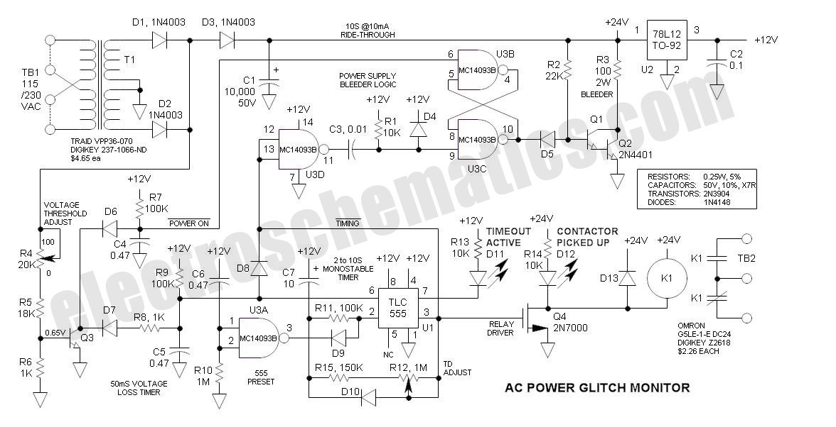
This AC Power Monitor continuously monitors the AC power line voltage for under-voltage conditions and missing cycles. When it detects a total of 5 or 6 consecutive anomalies, it triggers an alert. The AC Power Monitor is designed to provide...

This is a solar-powered flasher designed to deter nocturnal animals such as bats and cats from farmyards or residential premises. The device features a bright multicolored light. The solar-powered flasher operates by utilizing a solar panel to harness sunlight, converting...
This is a 300 W RF amplifier designed for FM transmission, capable of operating within the frequency range of 88 to 108 MHz. The amplifier utilizes two TP9383 transistors, enabling it to deliver up to 300 W of output...