
Power loss detector

The described circuit utilizes a silicon-controlled switch (SCS) as a key component for controlling the discharge of capacitor C. In the initial state, when a positive voltage is applied to the input, the current flows through the IN4148 diode, which is configured to allow current flow in one direction only. This charging action of capacitor C through resistor R establishes a voltage across C, while the SCS remains in its non-conductive state due to the blocking action of the diode.
When the input transitions to a negative voltage, it provides the necessary anode-gate current to the SCS, effectively triggering its conduction state. This transition allows capacitor C to discharge its stored energy through resistor R1. The discharge path is crucial for controlling the timing and duration of the output signal, which can be utilized in various applications, including timing circuits, pulse generation, and signal modulation.
The choice of components, such as the IN4148 diode, is significant due to its fast switching capabilities and low forward voltage drop, which enhances the efficiency of the circuit. Additionally, the values of resistors R and R1, along with the capacitance of C, must be carefully selected to achieve the desired timing characteristics and ensure stable operation within the specified voltage and current ranges.
Overall, the circuit effectively demonstrates the interaction between input signals and the control of energy storage and release via the SCS, providing a reliable mechanism for electronic control applications.A positive going input charges C through the IN4148 and R. The diode keeps the scs off. A negative going input supplies anode-gate current triggering on the scs discharging C through Rl.
Related Circuits
Construct a basic power failure alarm monitoring system utilizing an AC relay that activates a buzzer when the mains power supply is interrupted. The proposed power failure alarm monitoring system is designed to provide an audible alert during a loss...
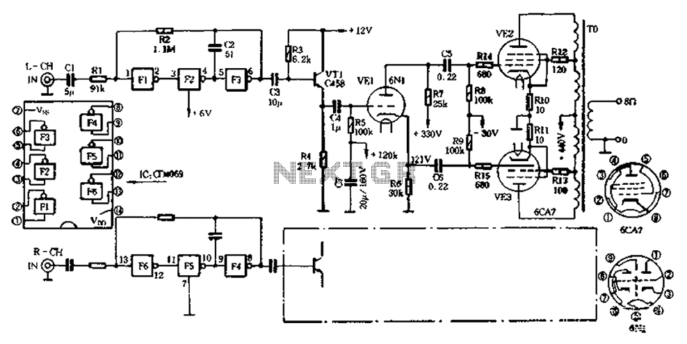
The CD4069 unit structure depicted in Figure 2-5 (a) consists of two abutment surfaces incorporated into a CMOSFET configuration. The input-output characteristics are illustrated in Figure 2-5 (b). Due to its superior unit switching curve, the CD4069 can be...
This application note demonstrates a simple 8-direction digital compass application utilizing Zilog's Z8 Encore!® MCU and an external compass sensor hardware. Communication ports are provided for the digital compass to receive commands and send status via the I2C bus...
Many antique radios operate on batteries, including tube portables like the Zenith model K-401 and "farm" radios used in rural areas without electrical power. This article provides historical context on battery usage in early radios and offers guidance on...
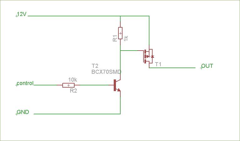
The schematic is attached. Suggestions for improvements are requested, particularly for adding reverse polarity connection protection. The logic level inputs (5 V) are designed to control two output voltages (12 V) using P-channel MOSFETs. The P-channel MOSFETs are ON...
The typical home solar power system primarily comprises a roof-mounted solar panel, a charge controller, and a storage battery bank, along with direct or electric connections. A home solar power system is designed to harness solar energy for residential use,...