
LM258 LM258 Flex Sensor Circuit

The circuit described incorporates an accelerometer and Hall effect sensors to facilitate the control and operation of a robotic snake arm. The accelerometer serves as a motion sensor that detects changes in orientation and movement, allowing for precise control of the snake arm's position and movement dynamics. It can provide data regarding tilt and acceleration, which can be processed to determine the desired mode of operation for the arm.
The Hall effect sensors are strategically placed to detect magnetic fields, which can be used to determine the position of the arm segments or to enable specific operational modes based on the proximity of magnetic objects or components. These sensors can trigger different functionalities, such as switching between modes for movement, grasping, or other tasks.
The integration of these components into a cohesive circuit requires careful consideration of the signal processing and control logic. The accelerometer output can be interfaced with a microcontroller, which interprets the data to adjust the arm's movements accordingly. The Hall effect sensors can also be connected to the same microcontroller, allowing for simultaneous processing of inputs to ensure seamless operation.
Power supply considerations must also be addressed, ensuring that both the accelerometer and Hall effect sensors receive adequate voltage and current for optimal performance. Additionally, protective components such as resistors and capacitors may be included to filter noise and stabilize the circuit.
Overall, this configuration provides a versatile platform for controlling a snake arm robot, enabling it to operate in various modes based on real-time feedback from the accelerometer and Hall effect sensors.used to select modes of operation, the accelometer is used to generally move the snakearm while the hall effect sensors are designed to enable .. 🔗 External reference
Related Circuits

This is a simple electronic thermometer circuit. It is an inexpensive circuit because the probe or sensor used in this circuit is a 2N2222 silicon transistor. The electronic thermometer circuit utilizes the 2N2222 silicon transistor as a temperature sensor. The...

This is a small circuit designed as an insect repellent, targeting mosquitoes and birds by producing high-frequency audio signals. These signals interfere with the hearing of insects, making it unbearable for them, causing them to flee. The operation of...

This design circuit is for a simple 27MHz transmitter that produces a carrier signal. The circuit generates an unmodulated 27MHz signal, which can be received by a compatible receiver. The transmitter operates as a basic crystal oscillator, with the...

The circuit illustrated in the figure features an automatic voltage regulator (T) that utilizes a servo motor to ensure a constant output voltage. The transistors used are VT1 and VT2 (3DK9C, with a range of 65 to 85) and...
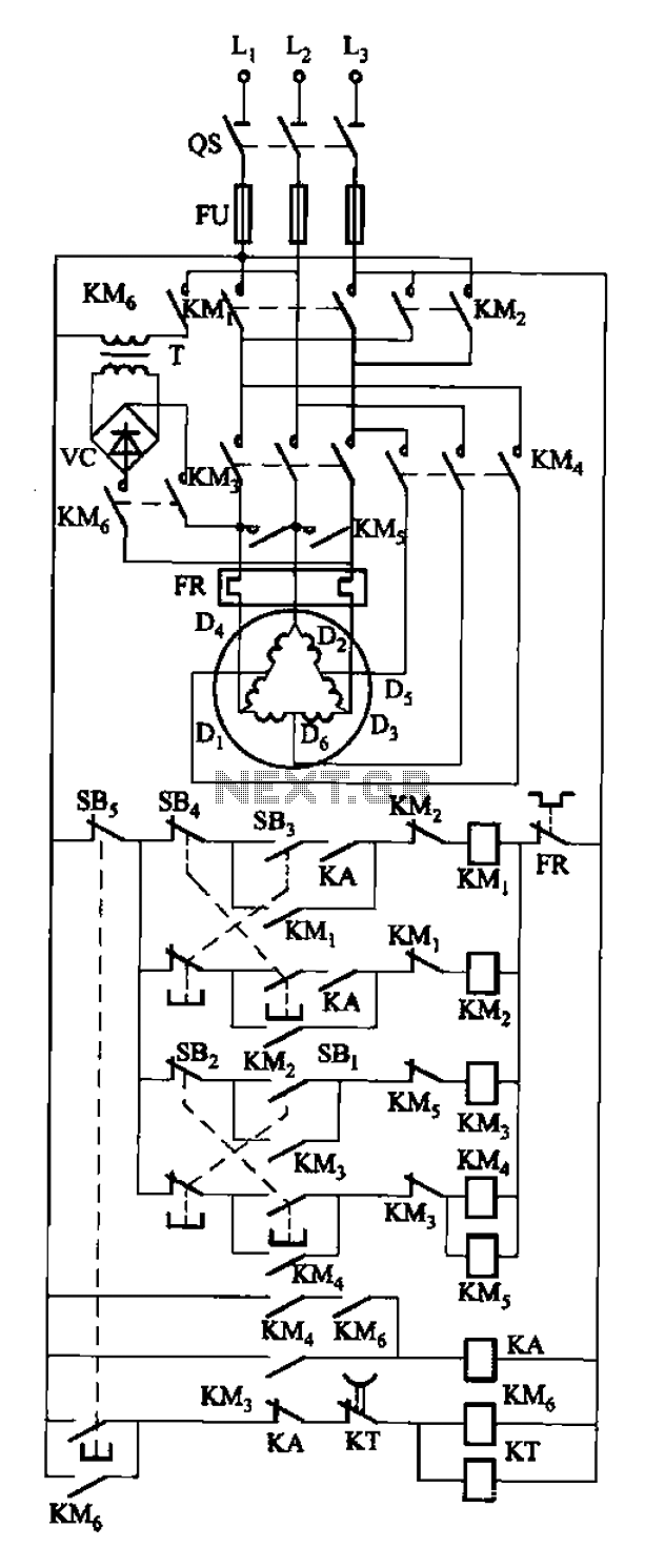
The circuit depicted in Figure 3-108 includes various control buttons: SB3 for the forward button, SI for the reverse button, SBi as the low start button, SB2 for the speed start button, and SBs for the stop button. KMs...

White LEDs have a rated current at a voltage drop of about 3.3 to 3.4 V. It is ideal to be powered from the battery voltage which is slightly larger. Then there is the best energy used. In this...