
circuit ultrasonic mosquito

The insect repellent circuit employs the 4047 integrated circuit, which is a versatile astable multivibrator capable of generating square wave signals at adjustable frequencies. The frequency output can be altered by changing the resistor and capacitor values connected to the IC, allowing for fine-tuning based on the specific pest being targeted. The circuit typically includes a power supply section, often utilizing a battery or a DC power source, which powers the 4047 and the associated components.
To enhance the efficacy of the ultrasonic signals, a piezoelectric speaker or transducer is commonly used as the output device. This component converts the electrical signals generated by the 4047 into ultrasonic sound waves, which propagate through the air to create a repellent field. The design may also incorporate a variable resistor or potentiometer, allowing users to adjust the output frequency to optimize performance against different types of pests.
In addition to the primary components, the circuit may include filtering capacitors to stabilize the power supply and prevent noise interference, ensuring that the ultrasonic signals are emitted at the desired frequency without distortion. A small LED indicator can also be integrated to provide a visual cue that the circuit is operational.
Overall, this ultrasonic insect repellent circuit represents an innovative solution to pest control, leveraging high-frequency sound waves that are inaudible to humans but effectively disrupt the behavior of unwanted insects and rodents. The adaptability of the circuit allows users to customize it for various applications, making it a practical choice for both residential and commercial pest management.This is a small circuit insect repellent, mosquitoes and birds, or other methods to produce high frequency audio signals. Interfere with the hearing of insects. Make it insufferable, wings to escape in the end. Operation of this circuit is used IC1 number 4047. A duty to produce frequency. MOSQUITO REPELLANT They will be swarming once again, the unwanted, winged torturers, looking for the victims
and leaving behind swelling and itch! The mosquito problem is a part of everyday life, espacially during the summer. Since the immemorial, inventive people have struggled hard to find effective means of protection against these insects. Even though it is a fact that only the females are dangerous, the males can also create situations of panic by their humming.
Ultrasonic Pest repeller circuit It is well know that pests like rats, mice etc are repelled by ultrasonic frequency in the range of 30 kHz to 50 kHz. Human beings can`t hear these high-frequency sounds. Unfortunately, all pests do not react at the same ultrasonic frequency. While some pests get repelled at 35 kHz, some others get repelled at 38 to 40 kHz 🔗 External reference
Related Circuits
The circuit on this page is for a simple light detector circuit board that has 8 detectors that can be used with visible or infrared light systems. The detectors use LM339 voltage comparators as the active element. Phototransistors or...
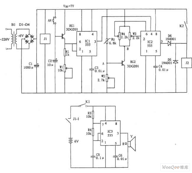
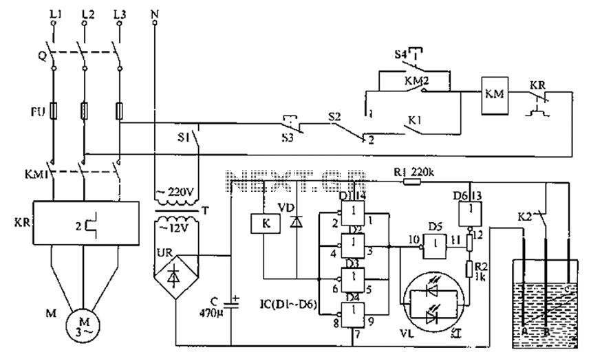
The figure illustrates the automatic watering control circuit for bean sprouts. The controller includes a step-down rectifier circuit, a power outage detection component (IC3), a timing control circuit (IC1), and a temperature control circuit (IC2). The step-down rectifier circuit...
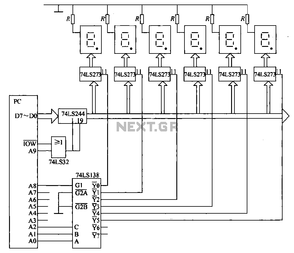
The static display circuit is illustrated in Figure 6. The 74LS244 acts as bus drivers, and six figures represent a public bus, each equipped with an LED display latch (like the 74LS273) connected to the code for latching the...

The circuit presented utilizes NAND logic gates from the Hitachi HD series, specifically the HD74LS00, which is a quad NAND integrated circuit. A special technique has been implemented to achieve three-state operation using a single IC. Gate N1 is...
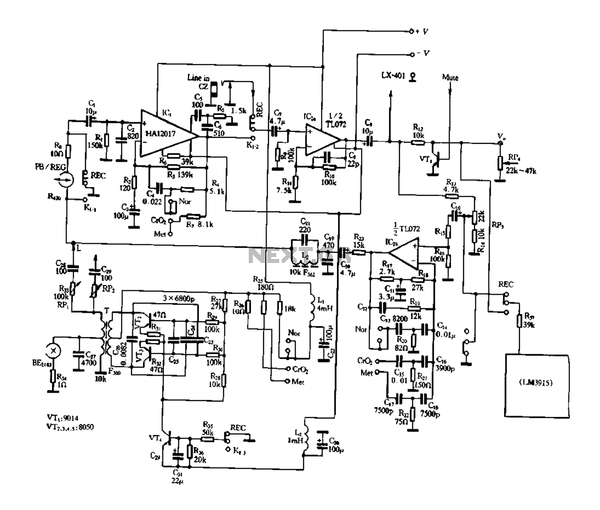
Figure 3-17 illustrates a pre-equalizer amplifier with sound recording capabilities, featuring the following characteristics: (1) The circuit does not utilize a conventional mechanical switch circuit; instead, it employs fully enclosed electromagnetic relays. This design allows for a core and...
The liquid level automatic controller circuit consists of a power circuit, a control instruction level detection circuit, and a starter control circuit. The power circuit is formed by a power transformer, a rectifier bridge, and a filter capacitor. The...