
lm317 variable power supply

The LM317 voltage regulator circuit is designed to provide a stable output voltage that can be adjusted according to the requirements of the application. The circuit typically consists of the LM317 integrated circuit, input and output capacitors, and resistors for setting the output voltage.
The input voltage must be higher than the desired output voltage by at least 3V to ensure proper regulation. The LM317 requires a minimum load current to maintain regulation, which can be achieved by connecting a load resistor if the actual load is too light.
For voltage adjustment, two resistors are connected in a voltage divider configuration between the output and the adjustment pin of the LM317. The output voltage (Vout) can be calculated using the formula:
Vout = 1.25V * (1 + R2/R1) + Iadj * R2
Where Iadj is typically very small and can often be neglected for most applications.
Input and output capacitors are recommended to ensure stability and transient response. A typical configuration might include a 0.1µF ceramic capacitor at the input and a 1µF tantalum capacitor at the output.
The LM317 is housed in a TO-220 package, which allows for easy mounting on a heat sink, ensuring that it can dissipate heat effectively during operation. This is particularly important when operating at higher currents, as excessive heat can lead to thermal shutdown or damage to the regulator.
In summary, the LM317 voltage regulator circuit is a robust solution for providing adjustable power supply voltages in various electronic projects, making it a staple component for hobbyists and professionals alike.A truly timeless circuit. LM317 is a versatile and highly efficient 1.2-37V voltage regulator that can provide up to 1.5A of current with a large heat sink. It`s ideal for just about any application. This was my first workbench power supply and I still use it.. 🔗 External reference
Related Circuits
The ADP1864 is a compact, cost-effective, constant-frequency current-mode step-down DC-DC controller. It drives a P-channel MOSFET to regulate an output voltage as low as 0.8 V with ±2% accuracy, handling load currents up to 5 A from input voltages...
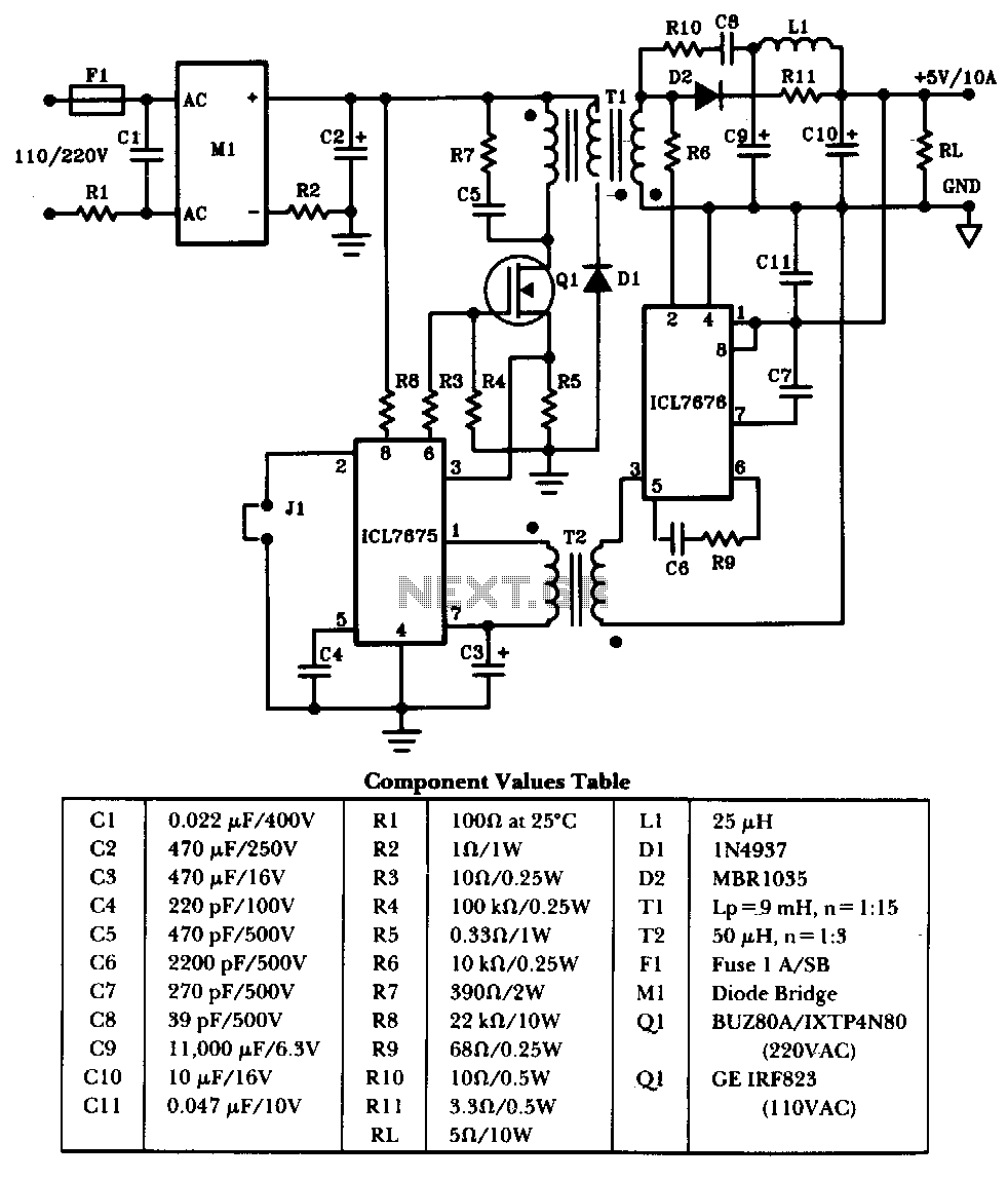
The schematic illustrates a 50W power supply providing a 5V, 10A output. It operates as a flyback converter in continuous mode. The circuit incorporates both primary and secondary side controllers, offering full protection against fault conditions such as overcurrent....
The Inter-Power SWR-5 upper right isn't worth a penny. Got it from a mate to use with a beacon, but I burnt it out with only 3.5-4W morse signal on 70cm. Removed the bridge and installed my own pick-up...
12W Audio Power Amplifier Circuit Diagram. Features: small power amplifier, excellent sound quality, incorporates a fully integrated design. The 12W audio power amplifier circuit is designed to provide high-quality audio amplification in a compact form factor. This amplifier is capable...
Integrated circuits (ICs) have largely replaced traditional circuits like this one; however, this circuit is still utilized where the flexibility of a discrete device design is desirable. The components are readily available, and the issue of IC obsolescence is...
This compact amplifier is built around the TDA2003 integrated circuit, which can deliver 4W RMS at a 4-ohm load. The TDA2003 offers enhanced performance while maintaining the same pin configuration as the TDA2002. It retains the advantageous features of...