
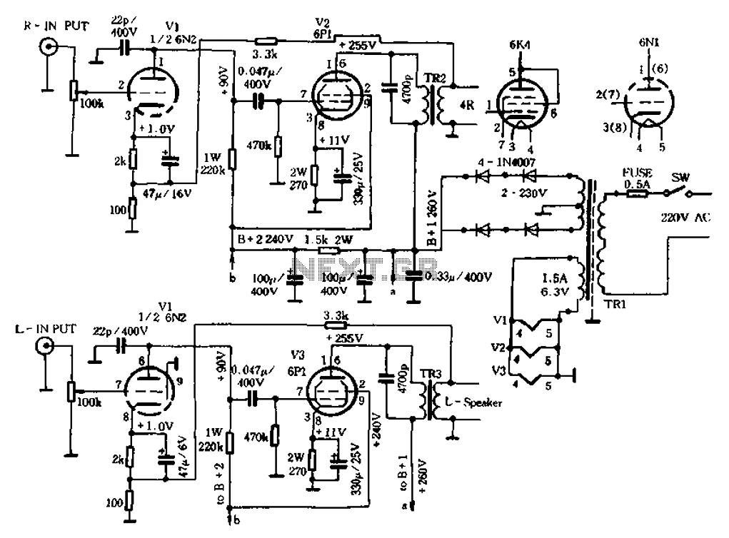
12W Audio Power Amplifier

The 12W audio power amplifier circuit is designed to provide high-quality audio amplification in a compact form factor. This amplifier is capable of delivering up to 12 watts of output power, making it suitable for driving small speakers or as part of a portable audio solution. The circuit typically utilizes a Class AB configuration, which balances efficiency and sound fidelity, ensuring minimal distortion and high linearity across the audio spectrum.
Key components of the circuit include a differential input stage, which enhances signal integrity and reduces noise. The use of transistors or operational amplifiers in the input stage allows for a wide dynamic range and improved signal-to-noise ratio. The output stage generally employs complementary push-pull transistor pairs, which contribute to the amplifier’s ability to handle varying loads while maintaining sound quality.
Power supply requirements for the circuit are generally modest, often operating within a range of 12 to 24 volts DC. This allows for compatibility with common battery-powered applications or standard power supply units. Capacitors are strategically placed throughout the circuit to filter power supply noise and stabilize the output, while resistors are used to set gain levels and provide feedback for improved performance.
Overall, the 12W audio power amplifier circuit is a robust solution for those seeking high-quality audio amplification in a small package, making it ideal for DIY audio projects, portable devices, or compact audio systems.12W Audio Power Amplifier Circuit Diagram. Features: small power amplifier, very good quality of sound, combines a completed very good quality .. 🔗 External reference
Related Circuits
A circuit for a bicycle horn utilizing a low-cost telecom ringer chip is presented. This design can be powered by a bicycle dynamo, eliminating the need for frequently replaced batteries. The circuit includes a half-wave voltage-doubler section formed by...
Power outages following a call prevent the re-closure of a circuit, which can help avoid the use of electrical appliances after the power grid is restored. If appliances are left on and a call occurs, it may lead to...
The 60 Watt linear amplifier is a simple all solid-state circuit using power MOSFET IRF840. The IRF series of power transistors are available in various voltage and power ratings. A single IRF840 can handle a maximum power output of...
The original radio circuitry has been transformed into a block diagram representation. The electrical schematic is illustrated in Figure 1-27, which depicts a typical single-tube amplifier of Group A. One figure represents the audio amplifier circuit for the original...
Most universal radio receivers have a very wide bandwidth that is not particularly suitable for radio amateurs. The better models with narrower bandwidth are almost a... Universal radio receivers are designed to operate over a broad frequency range, making them...
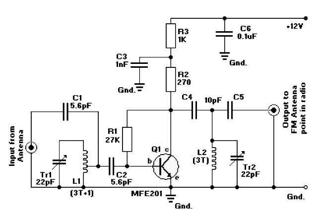
FM radio antenna amplifier circuit diagram. This amplifier will pull in all distant FM stations clearly. The active FM amplifier circuit is configured as a common-emitter tuned RF pre-amplifier wired around the VHF/UHF transistor MFE201. Below is a circuit...