
lm339 and bit of fun with accelerometer

The circuit design includes a voltage comparator to determine the state of the input voltage relative to half of the supply voltage (Vcc). The output of the comparator is connected to two LEDs, which will indicate the voltage level by illuminating one LED when the voltage is low and the other when it is high. This visual feedback is crucial for monitoring the system's performance.
For the motor control, the H-bridge configuration allows for bidirectional control of the motors. This is accomplished by using the two operational amplifiers to drive the gates of MOSFETs or bipolar junction transistors (BJTs) in the H-bridge. The design should ensure that the operational amplifiers are configured to switch states based on the comparator output, effectively allowing the motor to change direction based on the input voltage level.
The selection of motors with a 1:100 gear ratio is advantageous for applications requiring high torque, but attention must be given to the current requirements, especially under load conditions. The motors' stall current of 1A indicates that the power supply and H-bridge components must be rated appropriately to handle this load without overheating or failing.
To enhance the responsiveness of the motor control system, the feedback loop may integrate resistors and capacitors to stabilize the control signals and filter out noise. This can help in achieving a more stable operation, especially in dynamic environments like balancing robots.
In terms of gyro selection, alternatives to STMicroelectronics should be explored. Manufacturers such as Analog Devices, InvenSense, or Bosch Sensortec may offer suitable analog gyroscopes with favorable support for small businesses. The choice of gyro will impact the overall performance of the balancing robot, particularly in its ability to detect angular velocity and assist in maintaining balance effectively.
Overall, careful consideration of component selection, circuit design, and feedback mechanisms will contribute to a robust and efficient motor control system suitable for balancing applications.Here`s a simple schematic of one of the parts, the idea is that if the probed voltage is below half point, one LED will be on, otherwise second one will be on. Also, now I think I`ll need to oompff the power on this thing, proper dc motor with some gearbox that`ll have enough torque is 12V, I think (correct me if I`m wrong of course).
Now, I migh t actually ditch that transistor all together and just end up using two 741. Because the idea is to have H-bridge drive motor one or the other way depending on the input voltage. When its below 1/2 Vcc, one way, above - the other way. Will it work is a different matter, but I`ll save quite few transistors if that`s the case. Since my motor turned out to be crap, I want to try 2x 1. 5v-3v motors with 1:100 gear, loads of torque ! But they`re heavy, and need shit loads of current (0. 35A on 3V each !). Also from the video the motors look quite slow for a balancing robot, You mainly need fast motors so it can correct it before it leans too much And as with most fast and sensitive regulations you will likely need some resistors and caps in feedback loops to tune the response of the regulator.
I saw someone make a balancing robot using a 555 timer so you like try looking at that for ideas When stopped with pliers it draws about 1A, so that might be something to watch out for. If I had to design the h-bridge myself, I would probably have some cut-off protection once current draw goes over certain amount.
Speed is important too, but that can be cured with voltage. Motor is 1. 5V-3V, so I reckon I could get away with 3. 3 or even 3. 6V if need be, to make it faster. and I think I need to find analog gyro. I think ST have a chip that does that, but suckers don`t like to support small businesses and refuse to send me samples. So I`ll try avoid their parts. Any suggestion on that 🔗 External reference
Related Circuits
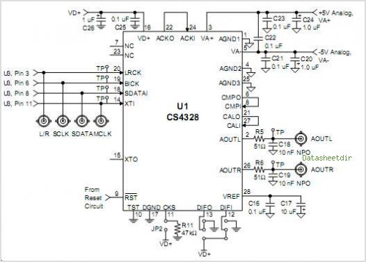
The CS4811 is a complete audio effects processing system integrated on a chip. This device features a proprietary 24-bit audio processing engine, substantial on-chip RAM, and a high-performance 24-bit audio codec. A serial control port enables the device to...
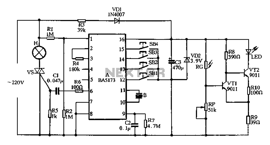
The circuit operates on a 220V AC input, which is stepped down by a buck converter using resistor R3. The output voltage is rectified by a VDI rectifier and filtered through VD2 and capacitor C3, providing approximately 3.9V DC...
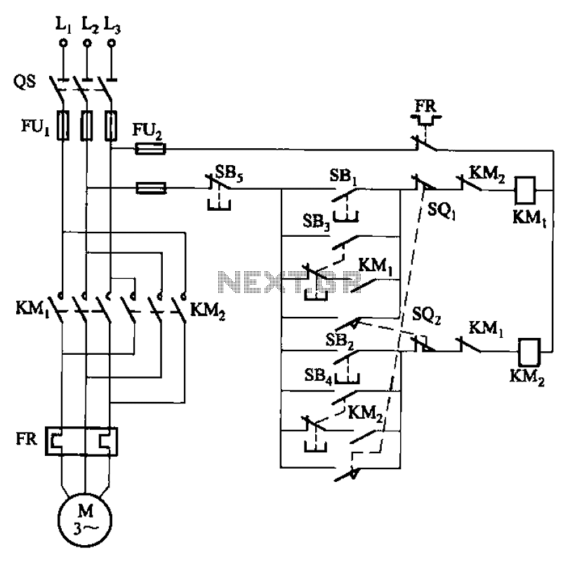
The circuit depicted in Figure 3-27 features a jog function that allows for precise adjustments of moving components. In the figure, SB3 and SB4 represent the forward jog and reverse jog buttons, respectively. When the SB3 button is pressed,...
A function generator that operates within a frequency range of 0.1 Hz to 20 MHz can be easily constructed using the MAX038 integrated circuit chip. This describes a straightforward implementation of the device. The MAX038 is a precision waveform generator...
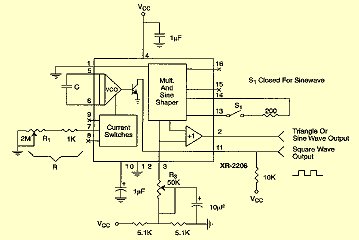
For measurement purposes in the electronics laboratory, signals of various frequencies and waveforms are frequently required. A standard function generator typically provides sine, triangular, and square wave outputs. The frequency must be adjustable and should encompass at least the...
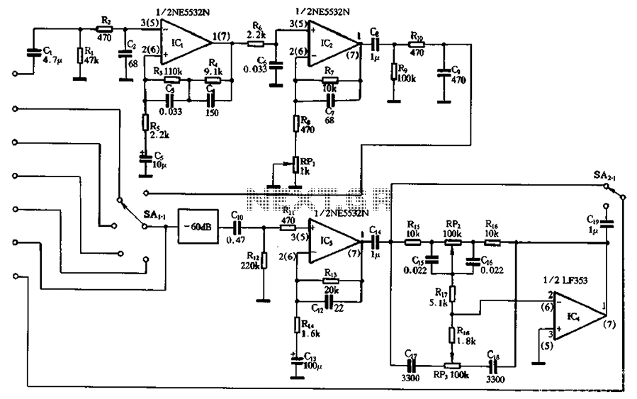
The circuit depicted involves a main amplifier balanced by an electromagnetic pickup, line amplifiers, and a high tone control circuit. It includes components for an electromagnetic player, radio tuner, tape playback, and line input. The preamplifier utilizes an NE5532...