
BA5173 produced by multi-function lamp dimmer

The circuit's design integrates several key components and functionalities that enhance its usability and effectiveness in managing light levels for eye protection. The buck converter configuration utilizing R3 efficiently steps down the AC voltage to a manageable DC level suitable for the BA5173 block. The rectification and filtering stages ensure stable voltage supply, critical for the reliable operation of the control logic and output stages.
The Schmitt trigger circuit involving VT1 and VT2 provides a robust method for detecting light intensity changes. The use of a photoresistor RG in conjunction with the Schmitt trigger allows for a responsive and reliable indication of ambient light levels. The chosen threshold of 100 lux serves as an effective point for activating the LED indicator, providing immediate feedback to users regarding their lighting conditions.
The control buttons (SB1 to SB4) introduce a user-friendly interface for adjusting light settings. The stepless dimming feature via SB1 allows users to gradually adjust brightness levels, accommodating varying preferences and needs. The stepped dimming function of SB2 offers simplicity with predefined levels, making it easy for users to switch between different brightness settings quickly. The delay-off feature of SB3 promotes energy efficiency and convenience, particularly useful in scenarios where users may forget to turn off the lights. Finally, the automatic on/off function of SB4 encourages regular breaks, thereby supporting eye health during extended reading or studying sessions.
Overall, this circuit design is a practical solution for managing lighting conditions in educational settings, combining functionality with user-centric features to promote eye safety and comfort.220V AC by R3 buck figure, VDI rectifier, VD2 and C3 filtered output voltage of about 3,9V DC supply set to block BA5173 electricity. Rl is manifold zero-crossing detector curr ent limiting resistor, R4 for the manifold external oscillation resistor, R7, C2 POR use, phasing BA5173 output trigger pulse through R6, CI added SCR vs gate to control the conduction angle. VTI, VT2 composition Schmitt circuit, it photoresistor RG and other elements constituting the metering display circuit, when the light shines greater than lOOlx (lux), the photosensitive resistor RG of less resistance, VT1 conduction, VT2 off, LED does not send light.
When the light intensity is less than lOOlx, RG resistance value increases, the Schmitt trigger circuit flip. VTI off VT2 conduction, LED light, indicating light is too weak, until transferred lamp dimmer so that the light intensity is greater than lOOlx, LED was extinguished.
This electrical path to avoid students under low light illumination to read and write, and thus play a role in eye protection. The circuit has four control buttons switches SB1 ~ SB4, each key switch the following functions: SBI: stepless dimming control keys.
When you use this key lights can be set to an arbitrary level, press this key, the lights fade from the dark, and then by repeated cycles of the brightest fade infinitely variable, when the light intensity reaches the extreme position (the brightest or darkest) when, the piezoelectric ceramic sheet B will uttered pops sound as a reminder, when transferred to the appropriate brightness, let go after the luminance namely memory retention. SB2: stepped dimming controls. Press the chain once, the light intensity changes in a block, press the low light, the light, the brightest and off 4 -speed dimming cycle.
SB3: Delay Off control keys. Button once, lights, after about half a minute after the lamp turns off automatically. It is suitable to sleep at night or when leaving the room to go out with. SB4: time automatic on/off control button. Press the button, lights, lights automatically turn off after about 20min, another 5nun light, bright 20rrun, repeated cycles. It is mainly used to remind students not read for a long time, in order to protect the eyesight, can also be used for night time outside confuse no one at home, so that thieves will not dare to patronize.
One thing to note, no matter what kind of light is dimming state, when the lamp is lit, to turn off the lights, just a short temporary Touch SB1 ~ SB4 any of a button, the lights are off. Readers can choose according to the actual needs of the above-mentioned one or several dimming mode.
Related Circuits
To create a battery-operated LED lamp, it is preferable to utilize a cluster of low-power discrete LED arrays instead of a single high-power LED. This configuration allows for scattered light production, significantly reducing irritation or potential damage to the...
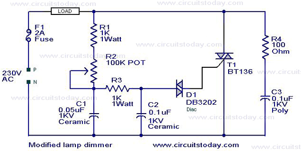
This is a modification of the Simple Lamp Dimmer/Fan Regulator circuit that was previously posted. The operation of the circuit remains the same as the original; however, it now includes a snubber circuit composed of resistor R4 and capacitor...
In this circuit, one, two or three neon indicator bulbs can be made to flash in sequence at rates determined by the R and C values. In the single stage circuit, using one lamp, the capacitor charges through the...
The circuit was designed to create a lamp that incorporates the operation of a touch dimmer using the S566B integrated circuit manufactured by Siemens. The circuit utilizes the S566B IC, which is specifically designed for touch-sensitive applications, to enable a...
The concept behind a light dimmer is to control the voltage supplied to a lamp or light source. Light dimmers regulate this voltage, allowing for an increase or decrease in light intensity. They first appeared in the market around...
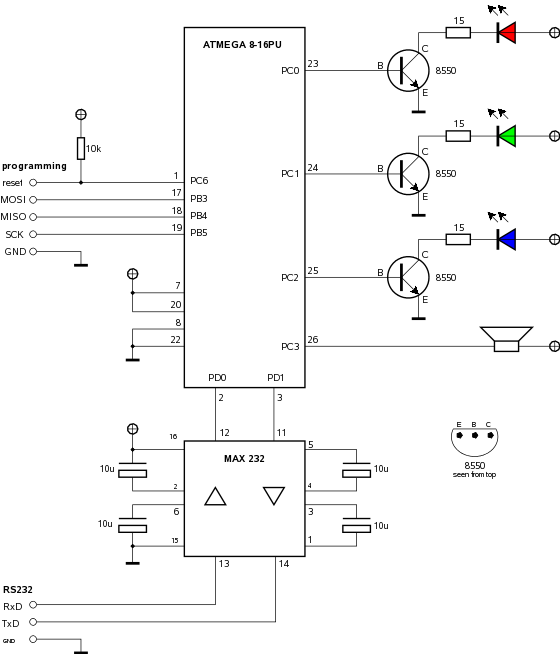
Building a computer-controlled LED lamp with an ATMEL microcontroller. The project involves designing a computer-controlled LED lamp utilizing an ATMEL microcontroller as the central processing unit. The core components of this circuit include the ATMEL microcontroller, a power supply, various...