
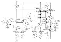
LM3886 two-channel audio amplifier circuit diagram

The described dual-channel circuit utilizing the LM378 operational amplifier is engineered for efficient audio amplification, delivering 4W per channel at a supply voltage of 24V. The choice of an 8-ohm load, or alternatively 16 ohms, allows for compatibility with various audio devices, ensuring versatility in application. The internal current limit and thermal overload protection circuits are critical features that safeguard the amplifier from damage due to excessive current or overheating, automatically disconnecting the output when thresholds are exceeded.
In terms of performance, the circuit's high ripple rejection ratio ensures that fluctuations in the power supply do not adversely affect audio quality, maintaining a clean and stable output. The high input impedance is advantageous for minimizing signal loss from the source, allowing for a more robust audio signal to be processed. Moreover, the design's emphasis on reduced external components simplifies the overall assembly and enhances reliability.
This circuit is particularly optimized for stereo applications, making it suitable for integration into various audio equipment, such as stereo tape recorders and FM/AM stereo audio power amplifiers. The inclusion of separate input termination enhances the circuit's ability to handle multiple audio sources effectively. Additionally, the bass and treble control features provide users with the ability to tailor the audio output to their preferences, allowing for an improved listening experience. Overall, this dual-channel circuit exemplifies a well-rounded solution for audio amplification needs in consumer electronics.FIG dual-channel circuit LM378 dual operational amplifier composed of Europe. Supply voltage Ub 24V and 8 ohm load (or 16 Euro), the output power per channel 4W. Circuit with i nternal current limit and thermal overload protection circuit cut off, etc., also has a power supply, which makes point bias voltage is automatically adjusted. In addition, it also has ripple rejection ratio, good channel separation characteristics, high input impedance and less external components and so on.
Particularly suitable for the stereo, stereo tape recorders, FM/AM stereo audio power amplifier for the radio. The circuit has a separate input termination action is high, bass control to limit the high, bass control to give the greatest degree of improvement and off.
Related Circuits
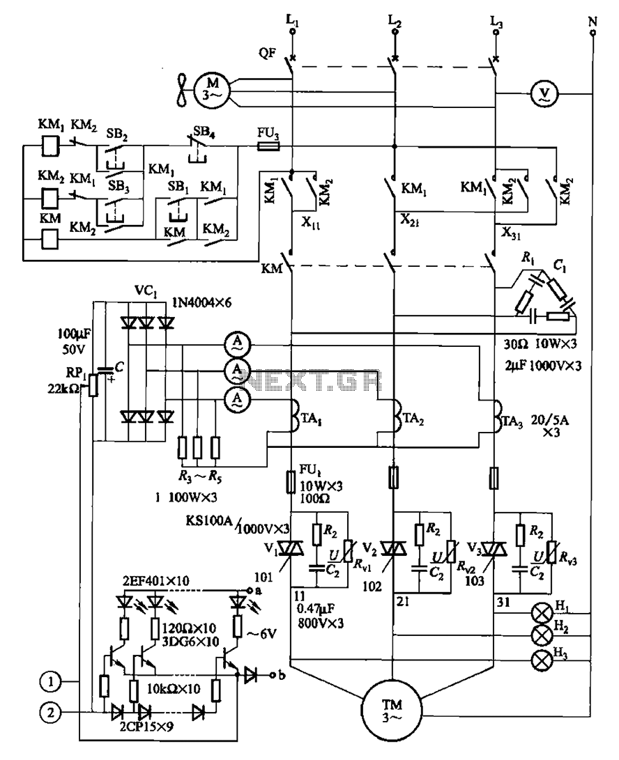
The circuit illustrated in Figure 3-178 is designed for controlling the speed and torque of a motor used in a continuous casting machine. It consists of the main circuit, a trigger circuit, and both manual and automatic control signal...
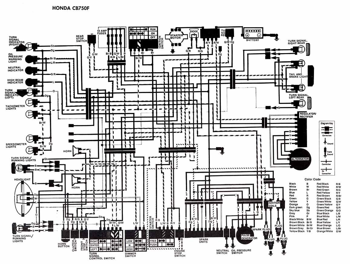
The following account presents the electrical wiring diagram for the Honda Motorcycle CB750F. It illustrates the connections between various Honda components, including the right turn signal indicator light, oil pressure warning light, neutral indicator, high beam indicator, turn signal...
This circuit combines two or more audio channels into a single channel (for example, mixing stereo into mono). The design allows for the addition of multiple channels, consuming minimal power. Although the schematic illustrates two inputs, it is possible...
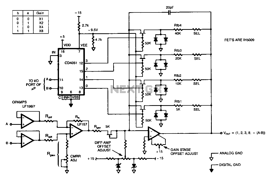
This programmable gain circuit utilizes a CD4051 CMOS Analog Multiplexer as a two to four line decoder, featuring appropriate FET drive for switching between feedback resistors to set the gain to one of four selectable values. The described programmable gain...
The following circuit illustrates the circuit diagram of a motor control unit. This circuit is based on the LM317 integrated circuit. Features include diodes that protect the regulator. The motor control unit circuit utilizes the LM317 voltage regulator to provide...
To configure the amplifier, set resistor R1 to its maximum value and resistor R12 to zero. After this adjustment, power on the amplifier. Adjust R1 until the measured output offset is between 30 mV and 100 mV. Once this...