
LM555 LED Blinkers

Two versions of the circuit are shown. The second circuit uses fewer components by taking advantage of the bipolar outputs of the timers. More: If the supply voltage is increased, a 1N4148 diode should be placed in series with light emitting diode D3. The values of the resistors should also be increased proportionately.
The described circuit operates using two independent timer circuits, which are typically implemented using a 555 timer IC or similar devices. Each timer is configured in astable mode to generate a square wave output that alternates the states of the connected light emitting diodes (LEDs).
In this configuration, when LED D1 is illuminated, the output of its corresponding timer circuit is high, which effectively turns off LED D2. Conversely, when LED D2 is lit, the output of its timer circuit is high, turning off LED D1. This creates a flashing effect between the two LEDs, ensuring that only one is lit at any given time.
LED D3 serves as an indicator that both D1 and D2 are off. This condition is monitored through a logic gate or a similar configuration that detects the low state of both timers' outputs. When both outputs are low, indicating that neither D1 nor D2 is illuminated, LED D3 turns on.
The circuit can be implemented in two variations. The first version may use discrete components, including resistors, capacitors, and transistors, to form the timer circuits. The second version simplifies the design by utilizing the bipolar outputs of the timer ICs, reducing the number of components required for the circuit's operation.
In cases where the supply voltage is increased, it is recommended to add a 1N4148 diode in series with LED D3. This diode will protect LED D3 from potential over-voltage conditions that could arise from the increased supply voltage. Additionally, it is essential to proportionately increase the resistor values in the circuit to maintain the appropriate current levels through the LEDs, ensuring their safe operation and longevity.
Overall, this circuit provides a simple yet effective means of controlling the operation of multiple LEDs based on timer outputs, with considerations for component selection and circuit protection.The circuit uses independent timers to flash two light emitting diodes. Any time that light emitting diode D1 is lit__light emitting diode D2 will be switched off. Light emitting diode D3 is on if both D1 and D2 are off. Two versions of the circuit are shown. The second circuit uses fewer components by taking advantage of the bipolar outputs of the timers. If the supply voltage is increased a 1N4148 diode should be placed in series with light emitting diode D3. The values of the resistors should also be increased proportionately. 🔗 External reference
Related Circuits

The LED traffic light circuit manages six LEDs (red, yellow, and green) for both north/south and east/west traffic directions. The timing sequence is produced using a CMOS 4017 decade counter in conjunction with a 555 timer. Outputs 1 through...
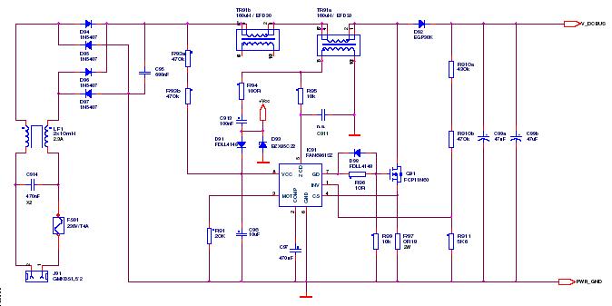
This article outlines a proposed solution for a 200 W power supply utilizing the FSFR2100 Fairchild Power Switch (FPS). The input voltage range is 90 to 265 VRMS, and it features six outputs. The 200 W power supply circuit based...

A very simple LED torch can be designed using the NSI45090JDT4G adjustable constant current regulator (CCR) from ON Semiconductor, utilizing very few external components. The NSI45090JDT4G device provides a cost-effective solution for regulating current in LEDs. This constant current...
Hello everyone. This is my first post in quite some time. I obviously do not have an old enough catalog for reference. In the data section, there were references to... The input data indicates a lack of sufficient information regarding...
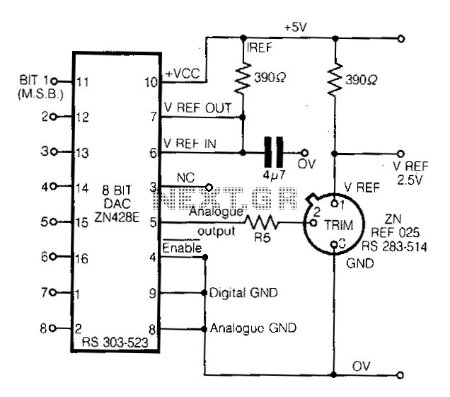
This circuit demonstrates a straightforward approach to achieving a voltage reference that can be adjusted using an 8-bit Digital-to-Analog Converter (DAC) equipped with an integrated voltage reference. The analog output from the DAC controls the trim pin of the...
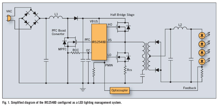
There is significant sensitivity to operating costs when managing high-powered commercial lighting. In these applications, there is a heightened focus on energy efficiency and AC line power factor, as these parameters influence operating expenses. Electric utilities impose additional charges...