
led traffic lights

The LED traffic light circuit is designed to provide a reliable and efficient means of controlling traffic signals at intersections. The circuit utilizes a CMOS 4017 decade counter, which counts from 0 to 10 and outputs a high signal on one of its ten output pins for each count. This functionality is crucial for generating the timing sequence required for the traffic lights.
The 555 timer is configured in astable mode, providing a continuous clock pulse to the input of the 4017 counter. The frequency of the clock pulse can be adjusted by changing the resistor and capacitor values connected to the 555 timer, allowing for flexibility in the timing of the traffic light sequence.
For the traffic light operation, the first four outputs of the 4017 counter (outputs 1-4) are utilized to control the red and green LEDs. The outputs are combined using diodes in a wire-OR configuration, ensuring that the red LED for the north/south direction and the green LED for the east/west direction are illuminated simultaneously during the first four counts. This arrangement allows for safe traffic flow in both directions.
On the fifth count (pin 10), the circuit activates the yellow LED for the east/west direction while simultaneously keeping the red LED illuminated for the north/south direction. This timing sequence effectively communicates to drivers when to stop and when to proceed, enhancing safety at the intersection.
The use of diodes in the circuit is essential for preventing backfeeding of current, which could potentially damage the LEDs or other components. The design is efficient and can be implemented using standard electronic components, making it suitable for various traffic management applications. Overall, this LED traffic light circuit serves as a simple yet effective solution for controlling traffic signals, ensuring orderly and safe vehicle movement at intersections.The LED traffic Light circuit controls 6 LEDs (red, yellow and green) for both north/south directions and east/west directions. The timing sequence is generated using a CMOS 4017 decade counter and a 555 timer. Counter outputs 1 through 4 are wire ORed using 4 diodes so that the (Red - North/South) and (Green - East/West) LEDs will be on during the first four counts.
The fifth count (pin 10) illuminates (Yellow - East/West) and (Red - North/South).. 🔗 External reference
Related Circuits
Catalyst Semiconductor, Inc. (NASDAQ:CATS), a supplier of analog, mixed-signal, and non-volatile memory semiconductors, announced it has received a patent for a unique step-down switching regulator circuit architecture applicable to step-down regulators for driving high brightness LEDs. The patent, titled...
This circuit drives up to four white LEDs in parallel from a 3.3V source and adjusts the total LED current from 1mA to 106mA in 64 steps of 1dB each. The circuit is designed for portable power applications that...
This indicator shows through a dual-LED see if a fuse is intact. The module is designed for 230 V AC. The green LED illuminates when the fuse is still good, the red lights when the fuse is broken. Perhaps...
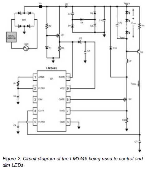
LEDs react much faster than conventional bulbs. Light dimmers for standard bulb-based lighting have been in use for many years. The most common implementation of such dimmers... LEDs, or Light Emitting Diodes, are semiconductor devices that emit light when an...
The circuit below illustrates powering one or two LEDs from the 120-volt AC line using a capacitor to drop the voltage and a small resistor to limit the inrush current. Since the capacitor must pass current in both directions,...
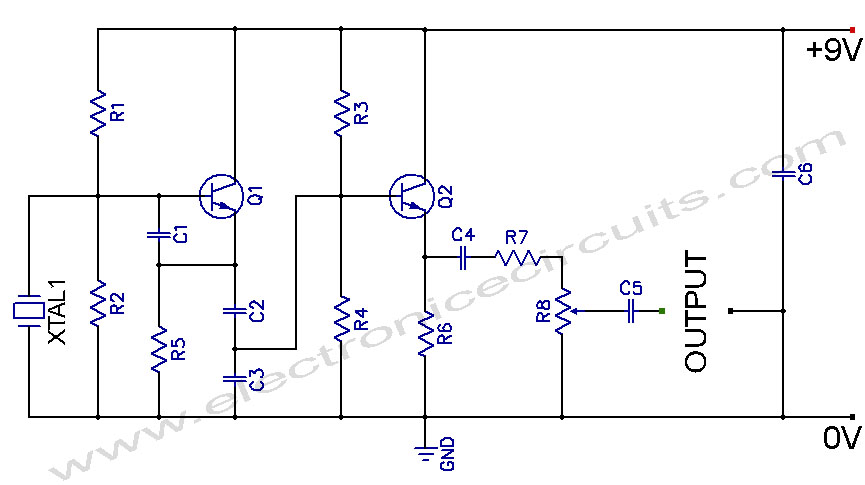
Crystal Controlled Oscillator Circuit. This general-purpose signal source is highly effective in signal-tracing applications. The output level is adjustable. The crystal-controlled oscillator circuit is designed to provide a stable and precise frequency output, which is essential for various electronic applications,...