
Logic Power Control circuit diagram for 78xx Regulator

The described circuit employs a logic-level control mechanism for managing the output of a linear voltage regulator, specifically the 78xx series, which is widely utilized for providing stable voltage outputs in various electronic applications. The circuit is designed to enable or disable the power supply to the load based on a digital control signal, thereby allowing for efficient power management.
In this configuration, a transistor acts as a switch that is controlled by a digital signal from a microcontroller or other digital logic device. When the control signal is high (logic 1), the transistor is turned on, allowing current to flow through the 78xx regulator, which in turn supplies power to the connected load. Conversely, when the control signal is low (logic 0), the transistor is turned off, interrupting the current flow and effectively shutting down the power to the load.
The use of TTL or CMOS logic levels ensures compatibility with a wide range of digital circuits. The transistor is typically an N-channel MOSFET or an NPN bipolar junction transistor, chosen for its low on-resistance and fast switching characteristics. The 78xx series regulator is selected according to the desired output voltage and current requirements, with common options including 7805 for +5V, 7812 for +12V, and 7809 for +9V outputs.
Additional components may include pull-down resistors to ensure the transistor remains off when the control signal is not asserted, as well as decoupling capacitors to stabilize the output voltage and reduce noise. The overall design promotes energy efficiency by allowing the power supply to be turned off when not needed, thereby minimizing power consumption in battery-operated or energy-sensitive applications.
This logic power control circuit is particularly advantageous in scenarios where digital control is essential, such as in EEPROM programming, where precise power management is critical to prevent data corruption during programming cycles.Logic power control of analog regulator can be useful in application where a digital circuit/controller need to control power source, such as in EEPROM programmer or other power controls. This is a circuit provide ON-OFF control for 78xx regulator using digital (TTL or CMOS) signal level.
This circuit uses transistors in series with the 78XX regulator, which.. 🔗 External reference
Related Circuits
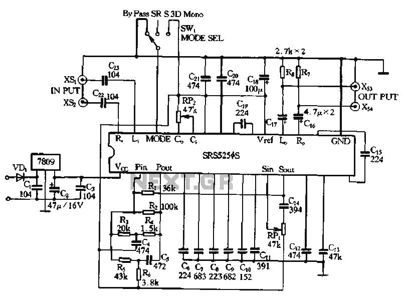
Typical application circuits for the Zheng brick SRS5250S are illustrated in the provided diagram. The SRS5250S features a pin diagram and a processing circuit that allows the user to switch between three operating modes: straight, SRS, and single-channel analog...
Charging a mobile phone or cellphone battery presents a significant challenge while traveling, as a power supply source is often not readily available. If the cellphone remains switched on continuously, its battery can deplete within five to six hours,...
Zilog's Z8 Encore XP F1680 Series features a highly optimized set of capabilities specifically designed for stepper motor microstepping control. Key features of the Z8 Encore! XP F1680 include: an 11 MHz internal oscillator, two analog comparators, a 10-bit...
This is a schematic diagram of a stereo audio amplifier for a car. The circuit is powered by a single IC, the TDA1553, along with some external components. This IC is designed to manage the stereo car audio system....
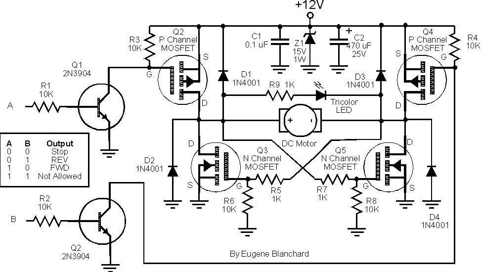
At 9 volts, the maximum stalled current of the motor types intended for use will be 700 mA. The selection of appropriate MOSFETs is crucial, particularly regarding their ratings for current and voltage handling. However, there are concerns about...
The primary issue with the design of a stereo amplifier that includes a total bass driver is that the signals from the left and right channels eventually become combined. This summation process minimizes the separation between channels, compromising the...