
Logic Probe

The described logic probe functions as a diagnostic tool for digital circuits, utilizing a single CMOS integrated circuit (IC) to indicate the state of the logic levels present at its input. The probe is capable of displaying three distinct logic conditions: High, Low, and Pulsing. These states are visually represented through the use of LEDs, which illuminate based on the voltage level detected at the probe's input.
In the high state, the probe detects a voltage level that is above a certain threshold, typically around 2.5V for CMOS technology, and the corresponding LED will light up to indicate this condition. Conversely, when the input is in the low state, which is generally below 0.8V, another LED will illuminate to signal this logic condition. The pulsing state occurs when the input is transitioning between high and low states, indicating that the circuit is actively switching, which is crucial for debugging timing issues in digital circuits.
An important feature of this logic probe is its ability to handle the high impedance state of tri-output logic ICs. When the probe is connected to an output that is neither driven high nor low (i.e., in a high impedance state), the LEDs remain off. This prevents false readings and ensures that the probe only indicates valid logic levels.
The power supply for the logic probe is sourced directly from the logic circuit under test, allowing for flexible operation across a range of voltages from 3V to 15V. This capability makes the probe versatile for testing various CMOS logic families, accommodating different logic levels without the need for an external power supply. The design, therefore, enhances the usability of the probe in various electronic applications, making it an essential tool for engineers and technicians involved in digital circuit design and troubleshooting.This logic probe uses a single CMOS IC and shows three logic conditions, High, Low and Pulsing. In addition if the probe input is neither hi or low (the high impedance state of tri-output logic ic`s) then no LED`s will light. Power from the logic probe is taken from the logic circuit under test; using a CMOS IC enables logic circuits to be tested using voltages from 3 to 15 volts.
🔗 External reference
Related Circuits
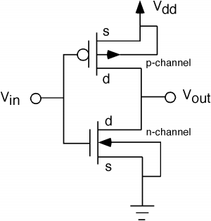
The fundamental issue presented is the perception that logic gates in a circuit seem to generate power from nothing, which contradicts the principles of physics. For instance, consider two NOT gates connected in series. It appears that the first...
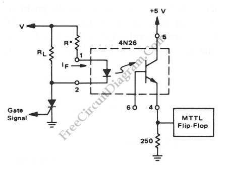
Interfacing high power loads can be accomplished in various ways, including the use of voltage divider resistors, transformers, or optocouplers. The circuit illustrated below employs the optocoupler method. This optocoupler facilitates logic level translation with flexible input, accommodating a...
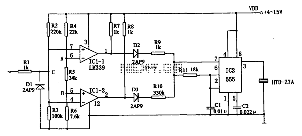
The acoustic logic level probe circuit consists of a voltage comparator, multivibrator, piezoelectric ceramics (HTD), and other components. The configuration of the audio circuit determines the frequency of the sound level to assess the logic levels of TTL or...
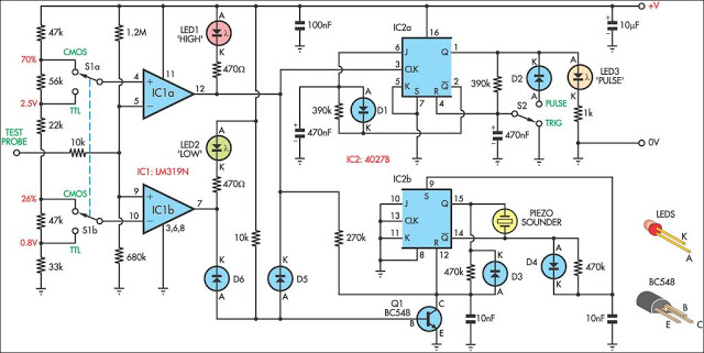
This logic probe can be selected to operate on TTL or CMOS logic levels, depending on switch S1. A string of resistors associated with switch S1 sets the threshold levels for a window comparator comprising IC1a and IC1b. Depending...
A Dual Inline Package (DIP) switch can be utilized to select between 0 and 5 volts in a circuit. Since the DIP switch lacks power or ground connectors, these must be provided externally. When the switch is in the...
Establish communication between the microcontroller unit (MCU) and the accelerometer using either I2C or SPI protocols. It has been noted that shorting the phase-locked loop (PLL) filter input in the device does not affect the readings from the gyroscope...