
Logic Probe With Sound

This logic probe circuit is designed to provide visual and auditory feedback for digital logic levels, accommodating both TTL (Transistor-Transistor Logic) and CMOS (Complementary Metal-Oxide-Semiconductor) logic families. The operation begins with the selection of logic type via switch S1, which influences the threshold levels established by a resistor network. The two resistors, 1.2MΩ and 680kΩ, are crucial in determining the midrange voltage at the probe when it is open-circuit, ensuring that neither LED is illuminated under these conditions.
The core of the circuit is the window comparator, formed by operational amplifiers IC1a and IC1b. This comparator monitors the voltage level at the probe and activates LED1 when a high logic level is detected and LED2 for a low logic level. The output from IC1a is also pivotal as it triggers the clock input of flip-flop IC2a when a pulse signal is present, allowing for dynamic response to incoming signals.
LED3 serves as an additional visual indicator, configured to either blink with each pulse or remain continuously lit, depending on the configuration of switch S2. This feature enhances the probe's functionality by providing real-time feedback on signal activity.
The outputs from the window comparator are routed through diodes D5 and D6 to the base of transistor Q1. This transistor functions as a switch, controlling the Reset input of flip-flop IC2b. The flip-flop is responsible for generating an audible output through a piezo sounder connected between its Q and Q-bar outputs. This design choice allows the circuit to produce a sound that corresponds to the input pulse signal, providing an auditory indication of logic states and transitions.
Overall, this logic probe circuit effectively combines visual and auditory indicators to facilitate the analysis of digital signals, making it a valuable tool for electronics troubleshooting and development.This logic probe can be selected to operate on TTL or CMOS logic levels, depending on switch S1. A string of resistors associated with switch S1 sets the threshold levels for a window comparator comprising IC1a and IC1b. Depending on whether the level applied to the probe is high or low, the window comparator turns on LED1 (high) or LED2 (low).
Th e 1. 2M and 680k resistors set the probe signal to a midrange value when the probe is open-circuit, thereby preventing either LED from being lit. If a pulse signal is present, the output of IC1a will toggle the clock input of flipflop IC2a. This drives LED3 which either lights for each pulse or continuously, depending on the setting of switch S2.
Finally, the outputs of IC1a & IC1b are connected by diodes D5 & D6 to the base of transistor Q1 which is connected to the Reset input of flipflop IC2b. This has a piezo sounder (not buzzer) connected between its Q and Q-bar outputs so that it produces a sound which echoes the input pulse signal.
🔗 External reference
Related Circuits
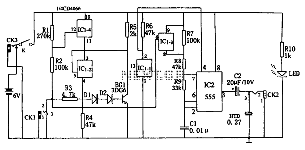
The circuit, illustrated in Figure five, employs a tri-state logic pen audio circuit. It primarily consists of a multivibrator, a four-way switch (CD4066, IC1), and several RC components. The multivibrator (555, IC2), along with resistors R7, R8, R9 and...
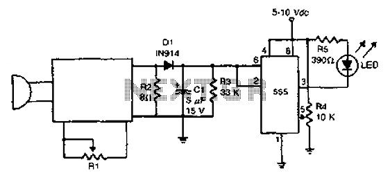
The acoustic detector consists of a Schmitt trigger IC555 connected to various components. When the input exceeds a certain voltage, the output will change state from high to low. R4 is used to set the threshold voltage. The acoustic detector...

The circuit operates as a light-to-sound conversion system, featuring a light electric sound conversion circuit with two simple fiber optic connectors for experimental purposes. The electrical diagram illustrates the conversion circuit, where audio signals from a radio, music player,...
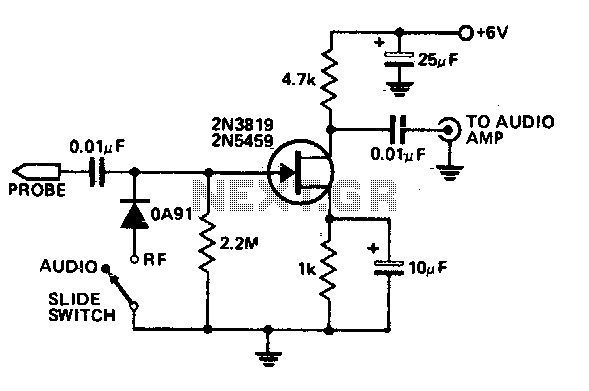
This economical signal tracer is useful for servicing and alignment work in receivers and low power transmitters. When switched to RF, the modulation on any signal is detected by the diode and amplified by the FET. A twin-core shielded...
The Magnitude Comparator is a device that compares two 4-bit binary inputs to determine their relationship, indicating whether one input is greater than, equal to, or less than the other. It outputs the conditions A > B, A =...
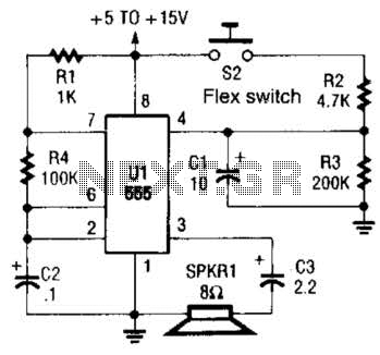
This is a cross-sectional diagram of a flex switch. They can be used as pushbuttons or even position sensors. This schematic diagram shows an oscillator, which is used as an alarm sounder, triggered by a flex switch. The flex switch...