
Logic Probe with PIC12F683

This project involves a logic state probe designed to measure voltage levels from TTL (5V) to PLC (24V) logic states. The core of the design is the PIC 12F683 microcontroller, which operates at a low voltage of 3V, making it suitable for battery-powered applications. The microcontroller features analog inputs and an internal oscillator, which simplifies the circuit design by eliminating the need for external clock signals.
The input stage of the circuit utilizes a voltage divider composed of resistors R3, D5, and D1. This voltage divider is crucial for setting a reference voltage level of approximately 2.80V at the microcontroller's input pin, which ensures that the system remains in a high-impedance state when there is no input signal. When an input signal, referred to as DATA IN, is applied, it alters the voltage at point H, allowing the microcontroller to discern whether the input voltage exceeds or falls below this reference threshold.
To manage power consumption, the microcontroller is programmed with an internal timer that puts it into sleep mode for approximately three minutes. During this period, the current draw is minimized to prolong battery life. The microcontroller is awakened by pressing a designated button, which restarts the measurement process, allowing for timely readings as required by the user.
The software configuration of the microcontroller is optimized for a 4MHz internal oscillator. The GP1 pin is designated for analog readings from point H, configured for a resolution of 10 bits. Additionally, GP2 is set as an input pin connected to a pull-up resistor and a secondary switch that grounds the pin. This configuration allows the microcontroller to detect button presses, which trigger an interrupt to initiate a timed loop. The interrupt service routine loads a value of 2000 milliseconds, after which the microcontroller returns to sleep mode to conserve energy.
The output stage of the circuit consists of three LEDs, each indicating different states: a yellow LED signifies high impedance, a green LED indicates a logic high (1), and a red LED represents a logic low (0). This visual feedback allows users to easily determine the state of the input signal at a glance. Overall, the design effectively combines low power consumption, adaptability to various voltage levels, and user-friendly output indicators.This project is based on a probe logic states, capable of measuring levels from TTL (5v) to state levels of PLC's (24v). For this we have employed the use of the PIC 12F683 microcontroller, which by its nature is capable of operating at low voltages, in this case 3vcc, besides having analog inputs and internal oscillator.
The circuit is supplemented by an input stage which will adapt the signal to the levels between the microprocessor is able to work and another output stage that will visually show the state in which the point is measured. The input stage to include a voltage divider between R3 D5 and D1, their role is to establish a fixed value (/ - 2.80) for the input of the microcontroller which means that is in a state of high impedance, ie without input signal. When we apply the input signal DATA IN this will vary the voltage drop at point H so that the reading as we discriminate if this is higher or lower than the reference voltage.
The program also has an internal timer to approximately 3 minutes between the microcontroller in sleep mode in which consumption will be minimal, to save the battery. And it will reactivate the program until you press the button, starting over allowing timing and take readings we require.
Focusing on the program of the microprocessor, this is configured to work with internal oscillation 4Mhz and configuring its pin so that analog reading take from point H by the GP1 pin, which is defined for a resolution of 10 bits, pin GP2 will also be defined as input and will be connected through a resistor (PULL UP) and a secondary switch to ground, which will be responsible for collecting the press that forced the interruption level change in GP2 While the interruption occurs loads a value (2000) as a timer to make a loop past work and this time will be placed the microcontroller in sleep mode. The output stage is made up 3 LED (yellow = high impedance, Green = Red = logic 1 and logic 0). 🔗 External reference
Related Circuits
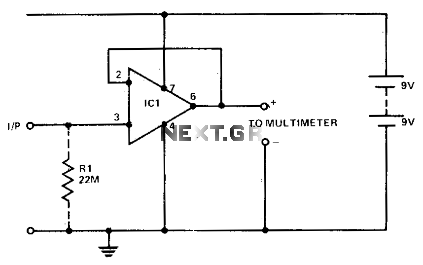
A 741 operational amplifier (op amp) is utilized with complete AC and DC feedback to achieve a typical input impedance of 10^11 ohms and unity gain. To minimize hum and radio frequency (RF) interference, it is recommended that the...
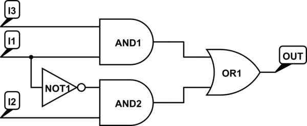
There are integrated circuits that contain AND, OR, and NOT gates. The inquiry revolves around the existence of a single chip that encompasses all the required logic gates. If such a chip does not exist, specific alternatives should be...
This circuit is a Logic Probe. It indicates the logic state of the node of any TTL logic circuit. To do that, we have to supply the probe with the same power of the circuit that we want to...
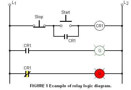
The relay logic circuit creates an electrical schematic diagram for controlling input and output devices. Components include resistors, capacitors, and others. The relay logic circuit operates by utilizing electromechanical relays to control various input and output devices in a systematic...
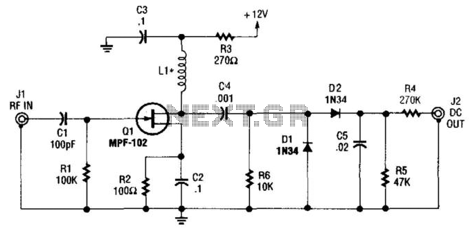
An MFP102 FET is utilized as a wideband amplifier. It can operate with an inductance (LI) of 100 µH for frequencies between 30 to 100 MHz or 1000 µH for frequencies between 2 to 30 MHz. For low frequencies...
NI Multisim software provides advanced virtual instruments and analysis tools that enhance the understanding of circuit designs. One such tool, the measurement probe, acts as a functional interface for observing circuit characteristics and customizing the simulation process within Multisim....