
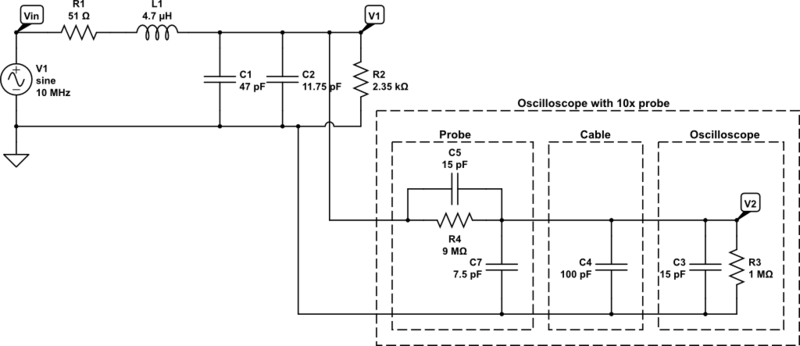
Pausing Simulation with the Measurement Probe in NI Multisim

With the measurement probe's advanced capabilities, users can access and display instantaneous voltages and currents at specific nodes, as well as pause simulations to review circuit performance. This feature is particularly valuable for designers, as it offers quick access to voltage, current, and frequency data at designated nodes during simulation. Multiple probes can be easily placed at any point in a circuit using the Instruments toolbar. Once connected to a node in a Multisim schematic, a yellow data region will display the time-varying characteristics of the circuit.
The measurement probe can also facilitate circuit analysis and simulation customization. For instance, users can configure the simulation to pause when a specific condition is met, allowing for verification of circuit functionality at predetermined intervals. In the Probe Properties dialog box, it is possible to set the probe to pause the simulation for a specified duration when a certain voltage value is reached at net 14 (e.g., when the voltage exceeds 2 V). To add a pause condition, the "New" button can be clicked, enabling settings to be adjusted in the window below for constructing the final expression. Users can input conditions either manually in the Condition(s) field or through pop-up menus.
To formulate the mathematical expression or Condition(s), the arrow button can be clicked to display relevant information. After selecting the Operators heading from the pop-up menu, the greater than sign (>) can be chosen, resulting in the Conditions field displaying "V>". When the circuit is simulated, the measurement probe will indicate a pause at each instance when the voltage at node 14 exceeds 2 V. If several probes are utilized in the schematic, this five-second pause allows designers to assess circuit characteristics during simulation, ensuring that when node 14 meets the preset condition, there is an opportunity to evaluate other currents and voltages of interest.
The measurement probe serves as a crucial tool in circuit simulation, providing real-time data and control over the simulation process. Its ability to pause simulations based on user-defined conditions enhances the designer's capability to monitor and analyze circuit behavior effectively. By leveraging the features of the measurement probe, engineers can gain deeper insights into circuit performance, leading to more efficient design and troubleshooting processes.NI Multisim software offers advanced virtual instruments and analyses to help you gain a deeper and more complex understanding of the operation of your design. One of these tools, the measurement probe, can be a quick and functional interface to the characteristics of your circuit as well as an advanced tool to customize the simulation process inMultisim.
With the advanced features of the probe, you can use the instantaneous voltages and currents at a particular node to access and display information in the Description Edit Box and pause your simulation as discussed in this article. An important feature for many designers, the measurement probe provides quick access to the voltage, current, and frequency of a particular node during simulation.
You can easily place multiple instances of the probe at any node of a circuit from the Instruments toolbar (circled in red in Figure 1). Once a probe is connected to a node on a Multisim schematic, a yellow data region immediately communicates the time-varying characteristics of the circuit as shown in Figure 2.
The measurement probe`s advanced features can also assist you in analyzing and customizing the simulation of a circuit. For example, you can set your simulation to pause based on a predetermined condition so you can check that a circuit is functioning properly during set increments of simulation.
In the Probe Properties dialog box, you can set the probe to pause simulation for a discrete amount of time when net 14 reaches a certain voltage value (in this case, whenever you reach a value greater than 2 V). 6. To add a pause condition, click on the New button (circled in red in Figure 3). This enables the settings in the bottom of the window to build the final expression. You can enter the condition at which an action is taken in one of two ways: manually enter it into the Condition(s) field OR enter it via pop-up menus as described below.
7. To create the mathematical expression or Condition(s), click on the arrow button (circled in blue in Figure 3). This displays the information shown in Figure 4. 9. Click on the arrow button (circled in blue in Figure 3) and select the Operators heading. In the pop-up menu, select the > (greater than) sign. Notice that the Conditions field now reads V>. Simulate the circuit and notice in the measurement probe that at each point that Multisim simulates a voltage value greater than 2 V at node 14, the simulator pauses.
If multiple probes are placed in the schematic, this five-second pause allows any designer to quickly take stock of the characteristics of a circuit during simulation, ensuring that when node 14 reaches the preset condition, there is an opportunity to check other currents and voltages of interest. 🔗 External reference
Related Circuits
The initial intention for this posting was to title it "Crystal Oscillator Blues," reflecting the challenges faced in constructing the crystal oscillator for the GPS Disciplined Oscillator (GPSDO), as mentioned in a previous post. However, there have been some...
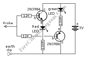
This is a simple logic probe circuit. A logic probe is used to determine if a point in a circuit has a high or low state when the circuit is in operation. The logic probe circuit is a fundamental tool...
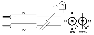
This circuit is not a novelty, but it proved so useful, simple and cheap that it is worth building. When the positive (Red) probe is connected to a DC positive voltage and the Black probe to the negative, the...
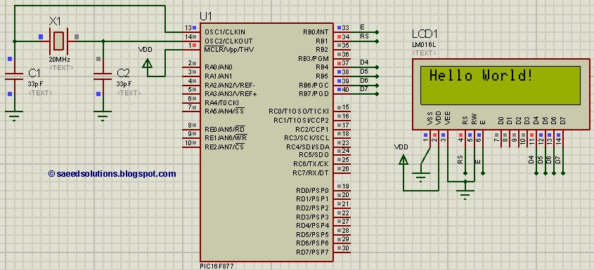
This tutorial on the PIC16F877 microcontroller addresses the question, "How to interface an LCD in 4-bit mode with the PIC16F877?" It also utilizes the PIC16 simulator (Proteus). The PIC16F877 microcontroller is a versatile device widely used in embedded systems. This...
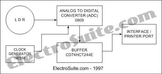
This is an illumination intensity measurement system diagram. The data in the microprocessor is always in digital form. This is an illumination intensity measurement system diagram - Part 1. The data in the microprocessor is always in digital form. The...
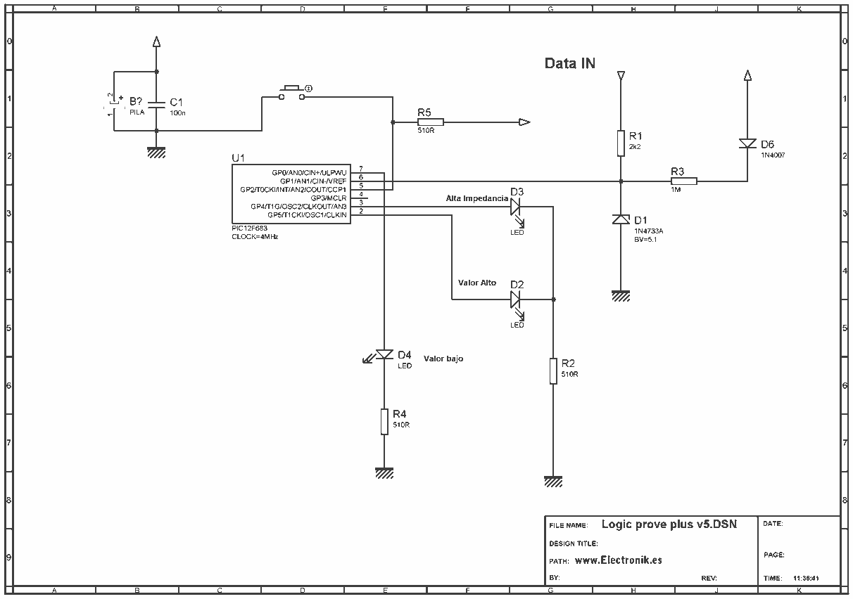
This project is based on a probe logic states, capable of measuring levels from TTL (5v) to state levels of PLC's (24v). For this we have employed the use of the PIC 12F683 microcontroller, which by its nature is...