
Logic Probe with Seven Segment Display

A logic probe is an essential diagnostic tool used in digital electronics to determine the logic level (high or low) at specific points in a TTL (Transistor-Transistor Logic) circuit. The probe provides a visual indication, typically through an LED, of whether a node is at a high (logic 1) or low (logic 0) state.
The operation of a logic probe requires a power supply that matches the voltage levels used in the TTL circuit, commonly +5V. The probe features a test lead that connects to the circuit node under investigation. When the probe is connected, it draws minimal current, ensuring that it does not significantly affect the circuit's operation.
Internally, the logic probe includes a voltage divider network and a comparator circuit. The voltage divider scales down the voltage at the probe's tip to a level suitable for the comparator. The comparator then compares this voltage to a reference level, typically set at approximately 2.5V for TTL circuits. If the voltage at the probe tip exceeds the reference level, the output of the comparator goes high, activating the LED to indicate a high logic state. Conversely, if the voltage is below the reference level, the LED remains off, indicating a low logic state.
The design may also incorporate additional features, such as a buzzer for audible feedback, or a switch to toggle between different logic levels (e.g., TTL and CMOS). This versatility enhances the probe's utility in various digital troubleshooting scenarios, making it a valuable instrument for engineers and technicians working with digital circuits.
The construction of the logic probe must ensure that it is compact and portable, with robust insulation on the probe tip to prevent accidental short circuits. The user interface should be intuitive, allowing quick interpretation of the logic levels without extensive training. Overall, the logic probe serves as a fundamental tool in the arsenal of electronic diagnostics, facilitating efficient troubleshooting and verification of digital systems.Logic probe is circuit that indicates the logic state of the node of any TTL logic circuit. It will work if we must supply the probe with the same power of.. 🔗 External reference
Related Circuits
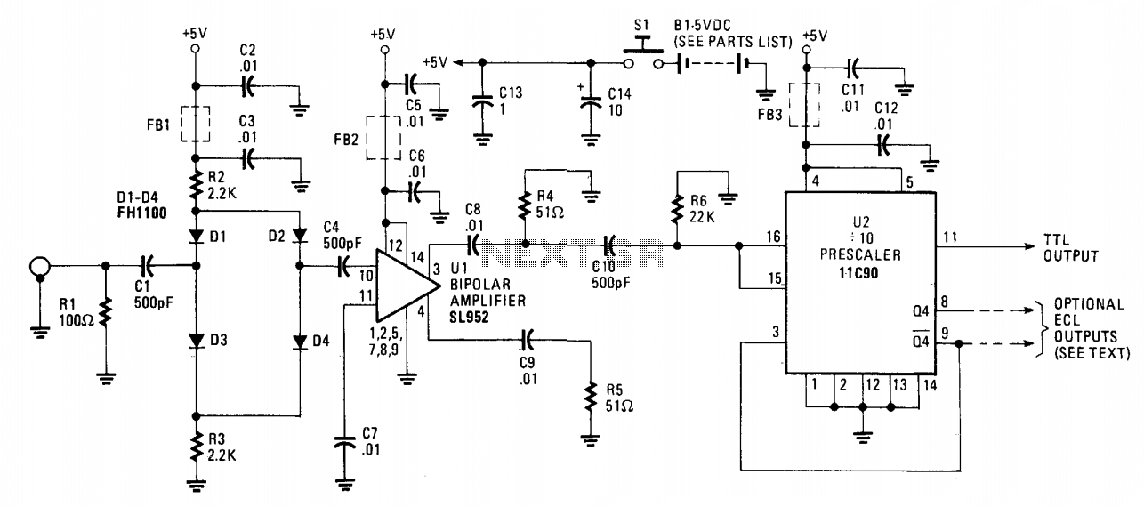
The 650 MHz prescaler probe's input is terminated by resistor R1 and is fed through C1 to the diode limiter composed of diodes D1 through D4. These diodes are forward-biased by the +5 volt supply for small input signals...
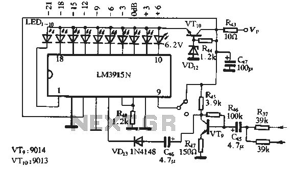
The circuit features a manual recording level control function. When in recording mode, the recording level is indicated by the LM3915N. The sound recording circuit, as illustrated in Figure 3-17, employs an RC network and an associated audio recording...
Connecting a LCD display to your personal computer is an easy job. Displaying data from your PC to a LCD can be proven very exciting, so give it a try and build your own today! In this article, we...
Since the output buffer of P1 can sink 20mA (each output pin, but maximum IOL for all outputs was limited at 80mA), thus we can use P1 to drive LED display directly. As shown in the circuit, Two common-anode...
Here is another project that creates a scrolling LED display. This display consists of 64 LEDs arranged in a matrix configuration. The anodes are driven through a driver circuit. The scrolling LED display project utilizes a matrix of 64 LEDs,...
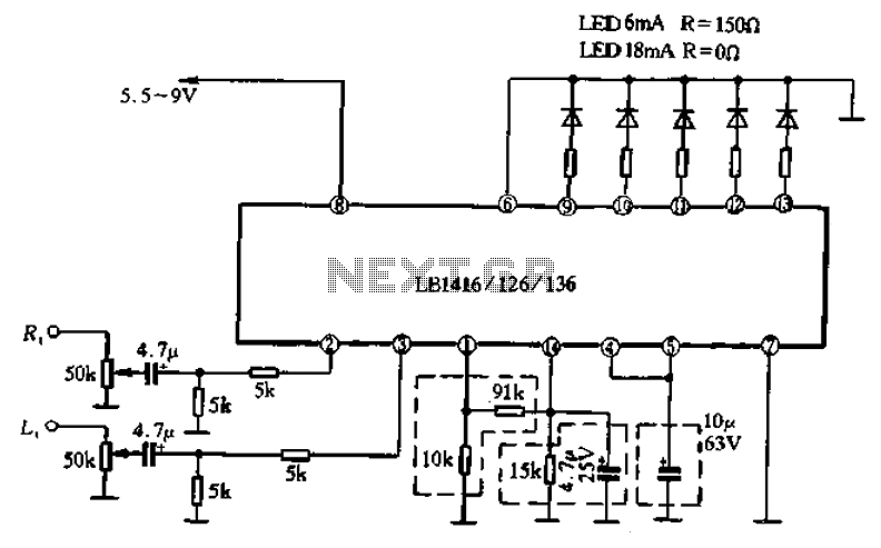
A common single five lamp drive circuit is the LB1416/26/36, which is packaged in a double row of finned-line 14 pins. The circuit contains two input amplifiers and five voltage comparators, allowing it to drive both AC and DC...