
7-Segment & Keypad

The circuit utilizes a microcontroller output port (P1) to directly drive two common-anode 7-segment LED displays. Each output pin from P1 can sink a maximum current of 20mA, allowing for direct control of the segments of the display while ensuring that the total output current does not exceed the specified limit of 80mA for all outputs combined.
In the configuration, a 180 Ohm current limiting resistor is placed in series with each segment of the LED displays to prevent excessive current from damaging the LEDs. The segments of the two 7-segment displays are connected in parallel to the output pins of P1, enabling simultaneous illumination of corresponding segments across both displays.
Transistors Q1 and Q2 serve as switches that are controlled by the logic levels on pins P3.0 and P3.1. When these pins are driven low, Q1 and Q2 are activated, allowing +5V to be sourced to the common anode pins of the LED displays. This configuration ensures that the segments can be illuminated by providing the necessary voltage to the anodes while controlling the cathodes through the P1 pins.
Additionally, pin P3.4 functions as an input that detects a logic low state when either switch S1 or S2 is pressed. This allows the system to perform a scanning operation to determine which switch is activated during the scanning period. The integration of these components facilitates the creation of an effective LED display driver circuit that can provide visual feedback based on user input.Since the output buffer of P1 can sink 20mA (each output pin, but maximum IOL for all outputs was limited at 80mA), thus we can use P1 to drive LED display directly. As shown in the circuit, Two common-anode 7-segment LEDs are connected to P1 with 180 Ohms current limiting resistor.
Each segment of two LED are tied in parallel to P1. Q1 and Q2 are activated by logic low of P3.0 and P3.1, sourcing +5V to common anode pins. P3.4 read logic low if either S1 or S2 was pressed while scanning period have made. 🔗 External reference
Related Circuits
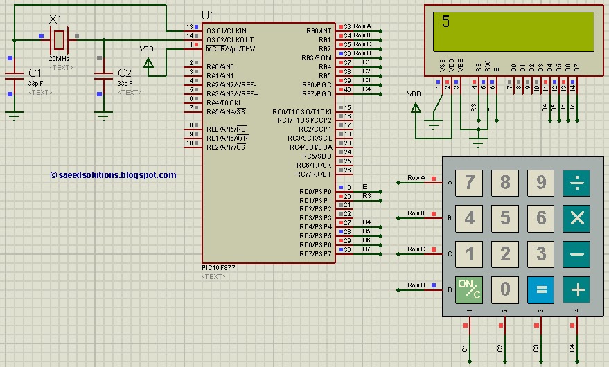
This PIC microcontroller tutorial provides a straightforward method to interface any keypad (e.g., 4x4 or 4x3) with the PIC16F877 microcontroller. This code is written... The tutorial outlines the steps necessary to connect a keypad to the PIC16F877 microcontroller, which is...
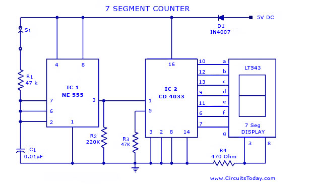
A simple seven-segment counter circuit with an LED display. This counter circuit diagram is designed using the IC CD 4033 as a counter, a 555 Timer IC, and a seven-segment LED display LT 543. The seven-segment counter circuit utilizes the...
This project can be used for many different purposes. Probably the most used application would be to interface to any electronic project that requires a keypad. There are several ready made keypads on the market, but those work with...
This Antenna is most widely used all over the world. For example, when you see a police car it has a transmitter with Ground Pole Antenna. The body of the car serves as ground. It accepts load from a...
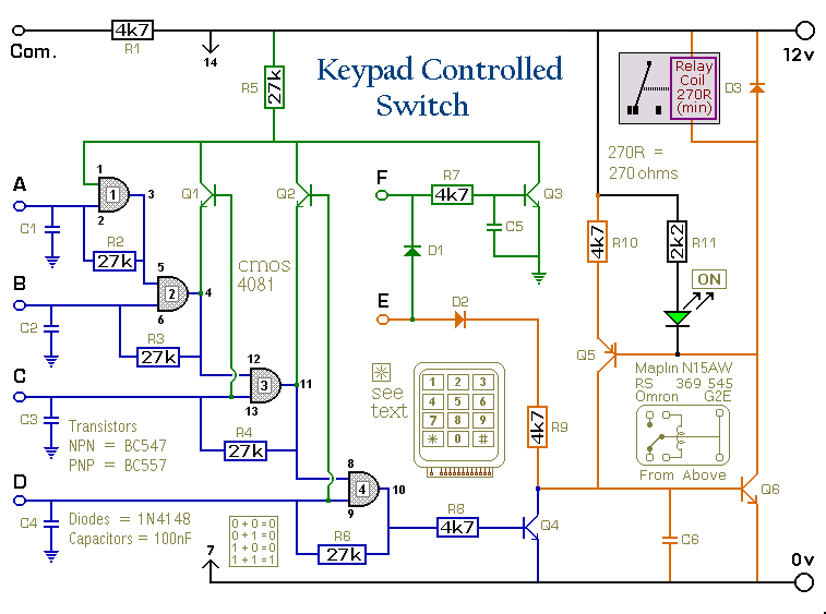
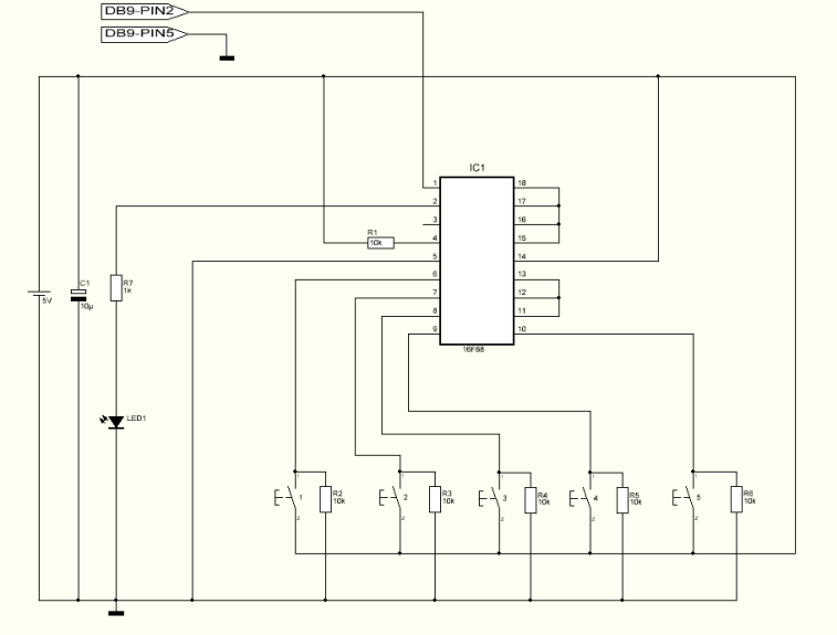
This is a universal version of the four-digit alarm control keypad. The design has been modified to free up the relay contacts, allowing the circuit to function as a general-purpose switch. A single pole changeover (SPCO) or single pole...
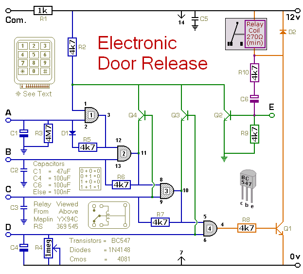
This circuit is designed to operate an electrical door-release mechanism, but it can also be used for other applications. Users can enter a four-digit code of their choice, which will energize a relay for a duration determined by the...