
Long distance infrared transmitter circuit diagram

The long-distance infrared transmitter circuit is designed to achieve an extended operational range by employing three infrared LEDs in series. This configuration not only amplifies the output power but also enhances the overall efficiency of the infrared transmission. The incorporation of a reflector, such as that found in a flashlight, allows for a more focused beam of infrared light, which is essential for long-distance applications, as it minimizes dispersion and maximizes the intensity of the emitted infrared signal.
In practical applications, the circuit can be utilized for remote controlling devices over significant distances, making it suitable for various remote control systems. The increase in complexity for achieving ranges greater than 5 meters is primarily due to the need for more robust components and careful circuit design to handle the increased power demands and maintain signal integrity.
The remote control tester circuit, based on the TSOP1738 infrared receiver module, serves as an essential tool for hobbyists and engineers alike. It provides a simple means to verify the functionality of infrared remote controls without requiring complex setups. The audible tone emitted by the tester upon receiving an IR signal acts as a clear indicator of successful communication, making it an invaluable resource for troubleshooting and testing.
The toy car control circuit exemplifies the practical application of infrared technology in consumer electronics. By utilizing the infrared transmitter-receiver pair, users can easily control the movement of the toy car, showcasing the versatility of infrared communication. The ability to modify the circuit for directional control adds an additional layer of functionality, allowing for a more interactive experience.
Temperature monitoring is another significant application of infrared technology, as demonstrated by the circuit featuring the LM35 temperature sensor. The dual LED indicator provides a straightforward visual representation of temperature thresholds, allowing users to monitor conditions effectively. This simple yet effective design illustrates the potential of infrared technology in creating practical solutions for everyday challenges.
Lastly, the battery level indicator circuit offers a visual method for users to assess battery status, which is particularly useful in portable devices. By employing a straightforward design, this circuit enables users to quickly gauge the remaining charge, promoting efficient usage and timely recharging of devices. Overall, these circuits showcase the diverse applications of infrared technology in electronics, highlighting its importance in modern electronic design.Long distance infrared transmitter circuit diagram. Here is a simple circuit that will give you a pretty long range. It uses three infrared transmitting LEDs (IR1 through IR3) in series to increase the radiated power. Further, to increase the directivity and so also the power density, you may assemble the IR LEDs inside the reflector of a torch. H ere the long range/distance Infrared transmitter circuit, give you extra power for your Infrared transmitter. The majority of the IR remotes do the job reliably within a range of 5 metres. The circuit complexity increases in case you design the IR transmitter for good operation more than a extended distance, for example, 10 metres.
To. Here is the remote control tester circuit. This circuit is really a simple and easy tester for verifying the basic operations of an infrared remote control unit. It is low-cost and very easy to construct. The tester is designed around infrared receiver module TSOP1738. Operation of the remote control is identified by a tone from. The circuit, consisting of an infrared transmitter-receiver pair, utilizes IR beam transmission to switch the toy car on` or off`, yeah.
it will be only switching on and switching off, you may modify this circuit to make the toy car to turn left or right. To operate the toy car, you have to hold the. This circuit is a circuit which will provide output indicator of the temperature around the circuit. The indicator is just 2 pieces LEDs (D1 and D2) which indicates the heat of above 80 degrees Celsius and below 80 degrees Celsius.
A well-known IC LM35 is chosen to be the temperature sensor in this circuit. Output. Here the circuit diagram of simple and easy made battery level indicator. In general, in mobile phones, the battery levels is displayed in dot or bar style. This helps you to effortlessly acknowledge the battery level. On this page we provide a circuit that helps you to recognize the battery level of a instrument from. 🔗 External reference
Related Circuits

The TDA7000 is a monolithic integrated circuit designed for mono FM portable radios or receivers, emphasizing minimal peripheral components for compact size and cost-effectiveness. This integrated circuit features a Frequency-Locked-Loop (FLL) system with an intermediate frequency of 70 kHz....

To invoke the Spectrum +3 diagnostic routines, first reset the machine while holding the BREAK key down. This will bring up the test card display. Next, hold down the QAZMLP keys for a few seconds until the diagnostic title...
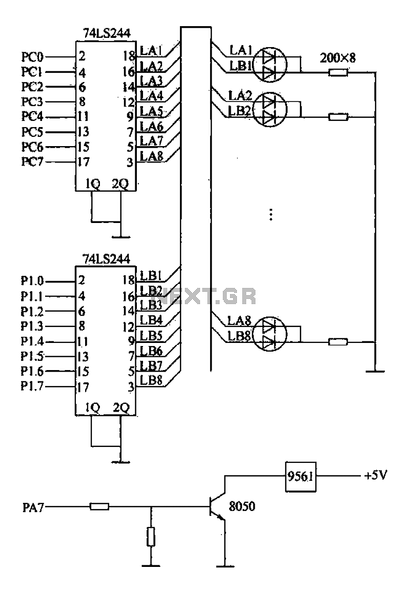
Alarm interface circuitry featuring a two-color light-emitting diode (LED) display. When LAi is at a high level and LBi is low, the green LED lights up; conversely, if LAi is low and LBi is high, the red LED lights...
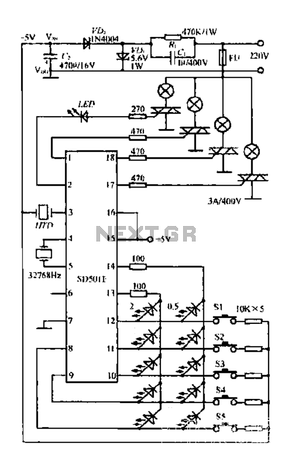
The FIG SD501E is a J tie fan integrated circuit (IC) characterized by progressive timing and three operational modes: strong, medium, and weak. It features three types of output settings and includes an electrical swing mechanism. The device is...
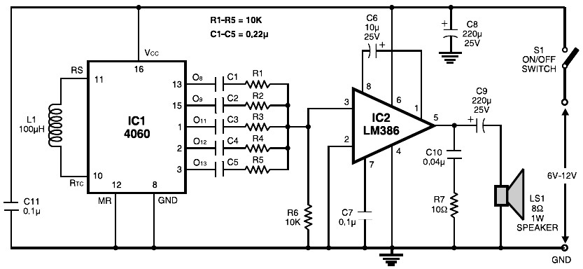
The circuit is built around the popular CMOS oscillator-divider IC 4060 and a small audio amplifier LM386. The IC 4060 functions as a multitone generator. A 100 H inductor is used at the input of the IC 4060, allowing...
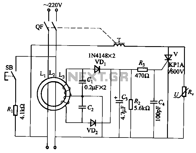
JBD3-10 leakage protection circuit The JBD3-10 leakage protection circuit is designed to detect and mitigate leakage currents in electrical systems, enhancing safety and preventing potential hazards. This circuit employs a differential current transformer that continuously monitors the current flowing through...