
JBD3-10 leakage protection circuit

The JBD3-10 leakage protection circuit is designed to detect and mitigate leakage currents in electrical systems, enhancing safety and preventing potential hazards. This circuit employs a differential current transformer that continuously monitors the current flowing through the live and neutral conductors. When a leakage current is detected that exceeds a predefined threshold, the circuit triggers a protective mechanism to disconnect the electrical supply, thereby preventing electric shock and equipment damage.
The schematic of the JBD3-10 leakage protection circuit includes several key components:
1. **Differential Current Transformer**: This component is crucial for sensing the difference in current between the live and neutral wires. It generates a secondary current proportional to the leakage current, which is then processed by the control logic.
2. **Microcontroller or Comparator Circuit**: The secondary current from the transformer is fed into a microcontroller or a comparator circuit that compares it against a predetermined threshold level. If the leakage current exceeds this level, the circuit activates the protective relay.
3. **Relay or Contactor**: This component acts as a switch that disconnects the electrical load from the power source when a leakage is detected. It ensures that the circuit is opened quickly to minimize the risk of electric shock.
4. **Indicator LEDs**: Visual indicators in the form of LEDs may be included to show the operational status of the circuit, such as normal operation, leakage detection, or circuit disconnection.
5. **Power Supply Circuit**: The circuit requires a stable power supply to operate the sensing and control components. This can be achieved through a dedicated power supply or by tapping into the monitored electrical system.
The design of the JBD3-10 leakage protection circuit must adhere to relevant safety standards, ensuring reliable operation under various conditions. Proper calibration of the threshold settings is essential to minimize nuisance tripping while maintaining adequate protection against dangerous leakage currents.JBD3-10 leakage protection circuit "0" cellpadding = "0" cellspacing = "2" method = "post" action = "/ e / search / index.php" obj.saytext.focus;} catcherr {}} catcherr {} $ function {$" # select_se ".changefunction {if $" # select_se ".val == 1 $" # show ".val title ; $ "#
Related Circuits
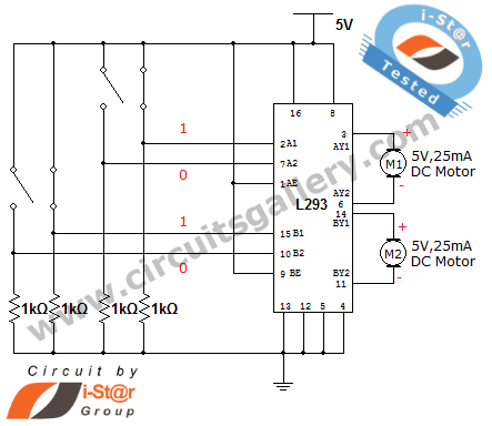
How can a DC motor be rotated in clockwise and counterclockwise directions? This is a common question posed by many robotics beginners. DC motor driver circuits are essential components in robotics workshops. The L293D IC is frequently utilized for...
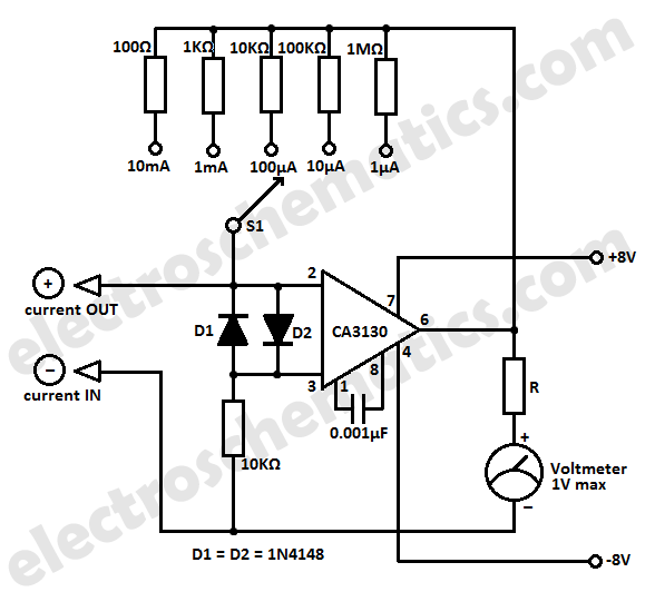
This LC meter circuit is capable of measuring inductors and capacitors. When either Lx or Cx is connected to the circuit, the oscillator frequency decreases, and this reduction is measured by a frequency-voltage converter constructed with transistors T3 and...
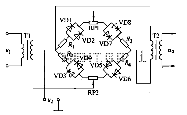
An AM diode ring circuit consists of four diodes arranged in a ring configuration, commonly referred to as a diode ring modulator circuit. This circuit offers significant advantages due to the characteristics of the diodes and the use of...
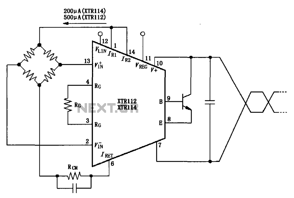
The two current sources within the chip (1 foot and 14 feet out) provide excitation. The output of each current source is 0.2 mA (XTR114) or 0.5 A (XTR112). The common mode input voltage is adjustable, ranging from 1.25...

A simple circuit that can generate an inverted square wave similar to the one used by the inventor on his function generator. To construct a circuit that produces an inverted square wave, a basic approach involves using a 555 timer...
Hi-fi headphones possess a wide frequency response and low distortion, making them incomparable to desktop Hi-Fi audio systems, particularly when compared to some branded headphones and even high-quality speakers. High-fidelity headphones are designed for music listening, offering high resolving...