
Long Period SCR Timer

The SCR timer circuit operates by utilizing a silicon-controlled rectifier (SCR) to control the activation of a buzzer based on a time delay determined by the combination of resistor R1 and capacitor C1. When power is applied to the circuit, capacitor C1 begins to charge through resistor R1. The charging time of C1 is governed by the RC time constant, which is calculated as the product of R1 and C1.
Once the voltage across C1 reaches a predetermined threshold, it triggers the gate of transistor Q1, which is configured as a field-effect transistor (FET). The conduction of Q1 allows current to flow to the gate of SCR1, turning it on. This action activates the buzzer, producing an audible sound to indicate the completion of the timing cycle.
The choice of a FET for Q1 is significant as it allows for a much higher RC time constant compared to a standard bipolar junction transistor (BJT). This characteristic enables the circuit to achieve longer time delays, making it suitable for applications requiring extensive timing ranges. The overall design is simple yet effective, allowing for easy adjustments of the timing interval by varying the values of R1 and C1.
In summary, this SCR timer circuit exemplifies a practical application of SCR technology in timing applications, with the ability to deliver long delays and a straightforward operational mechanism. The schematic diagram accompanying the description illustrates the connections between the components, highlighting the roles of R1, C1, Q1, and SCR1 in the timing process.This is a SCR timer circuit. Here, SCR is used to drive the final actuator, the buzzer. The time constanst of this circuit is determined by R1 and C1. The buzzer will sound when C1 charges up to a desired level, it will cause the Q1 to conduct and triggers SCR1. The use of FET for Q1 make the RC constant can be very high for very long time dela y, make this circuit has very wide range time setting. Here is the schematic diagram of the circuit: 🔗 External reference
Related Circuits
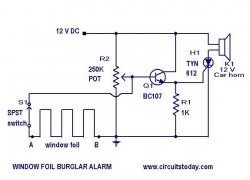
This is a simple yet effective burglar alarm circuit designed to be mounted on windows for detecting break-ins. The circuit employs a fine wire element arranged as a network within the window glass for sensing any breach. Under normal...
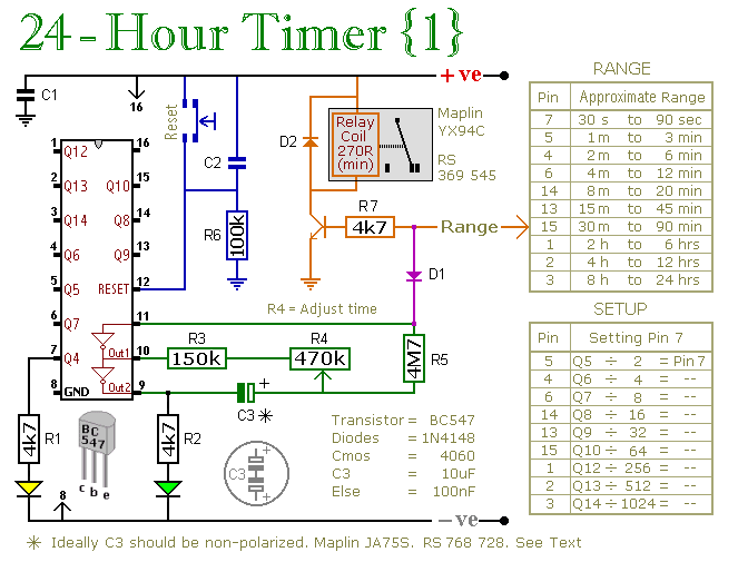
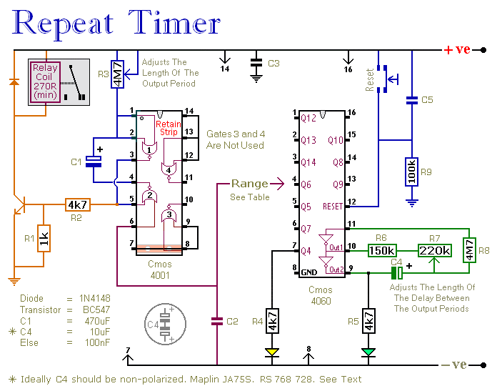
These two circuits are multi-range timers that offer periods of up to 24 hours and beyond. Both circuits are fundamentally similar, with the key distinction being that Version 1 energizes the relay when the time expires, while Version 2...
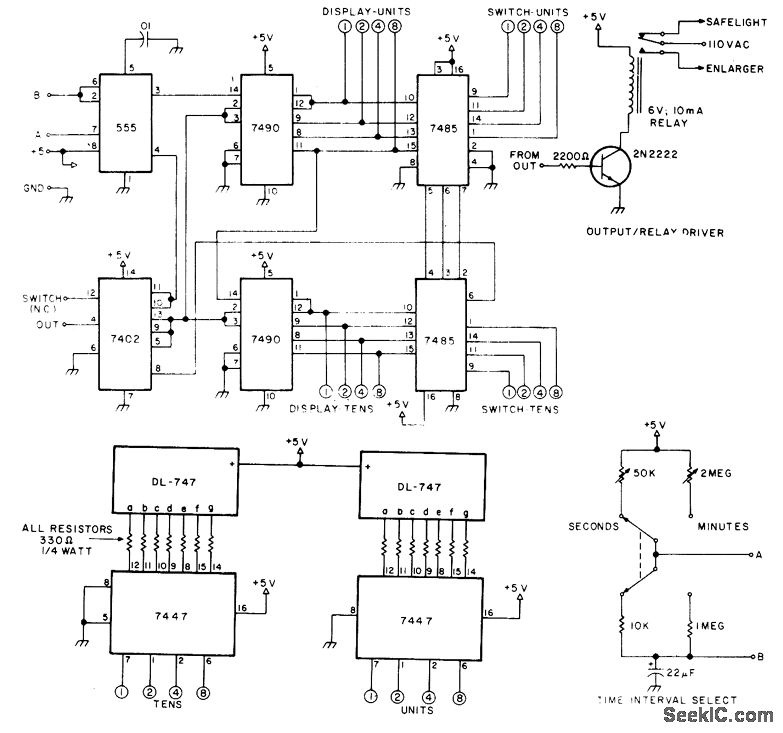
The circuit provides timing capabilities ranging from 1 second to 99 seconds and from 1 minute to 99 minutes, featuring a 2-digit LED indicator that displays the elapsed time. The desired timing interval is set using BCD thumbwheel switches....
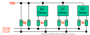
The I2C bus employs a bi-directional Serial Clock Line (SCL) and Serial Data Line (SDA). Both the SCL and SDA lines are pulled high using a pull-up resistor (Rp). An optional resistor (Rs) is utilized for ESD protection in...

This is a programmable clock timer circuit that utilizes individual LEDs to indicate hours and minutes. Twelve LEDs are arranged in a circle to represent the 12 hours of a clock face, while an additional 12 LEDs are positioned...
This circuit features an adjustable output timer that can re-trigger at regular intervals. The output duration can range from a fraction of a second to half an hour or more, and it can be configured to recur at intervals...