
24 Hour Timer

The circuit design features two distinct timer configurations, each utilizing the CMOS 4060 integrated circuit to achieve precise timing. The inherent versatility of this circuit allows it to be adapted for various applications, such as automated lighting systems, irrigation timers, or industrial control systems. The choice between energizing or de-energizing the relay upon timer completion can be crucial depending on the specific application requirements. The detailed schematic illustrates the connections between the CMOS 4060, resistors, capacitors, diodes, LEDs, and the relay, ensuring clarity in the design and facilitating troubleshooting.
The oscillator's frequency, determined by R3, R4, and C3, plays a critical role in the timing accuracy. It is imperative to select components that meet the specifications to maintain reliability. The use of a non-polarized capacitor is recommended to prevent any issues related to incorrect polarity, which could lead to circuit failure. The setup tables provide a systematic approach to establishing the desired timing intervals, significantly enhancing the user experience and reducing setup time.
The inclusion of a reset mechanism allows for flexibility in operation, providing the ability to restart the timer without disconnecting the power supply. This feature is especially useful in applications where timing adjustments are frequently required. The optional reset button, while not necessary, can enhance usability during testing and calibration phases.
Overall, this multi-range timer circuit is a robust solution for various timing applications, offering flexibility in design and operation while ensuring ease of use and reliability. The comprehensive support materials provided enhance the user experience, making construction and implementation straightforward for individuals with varying levels of electronics expertise.These two circuits are multi-range timers offering periods of up to 24 hours and beyond. Both are essentially the same. The main difference is that when the time runs out, Version 1 energizes the relay and Version 2 de-energizes it. The first uses less power while the timer is running; and the second uses less power after the timer stops.
Pick the one that best suits your application. The Cmos 4060 is a 14 bit binary counter with a built in oscillator. The oscillator consists of the two inverters connected to Pins 9, 10 & 11; and its frequency is set by R3, R4 & C3. The green Led flashes while the oscillator is running: and the IC counts the number of oscillations. Although it`s a 14 bit counter, not all of the bits are accessible. Those that can be reached are shown on the drawing. By adjusting the frequency of the oscillator you can set the length of time it takes for any given output to go high.
This output then switches the transistor; which in turn operates the relay. At the same time, D1 stops the count by disabling the oscillator. Ideally C3 should be non-polarized; but a regular electrolytic will work, provided it doesn`t leak too badly in the reverse direction. Alternatively, you can simulate a non-polarized 10uF capacitor by connecting two 22uF capacitors back to back (as shown).
Using "Trial and Error" to set a long time period would be very tedious. A better solution is to use the Setup tables provided; and calculate the time required for Pin 7 to go high. The Setup tables on both schematics are interchangeable. They`re just two different ways of expressing the same equation. For example, if you want a period of 9 Hours, the Range table shows that you can use the output at Pin 2.
You need Pin 2 to go high after 9 x 60 x 60 = 32 400 seconds. The Setup table tells you to divide this by 512; giving about 63 seconds. Adjust R4 so that the Yellow LED lights 63 seconds after power is applied. This will give an output at Pin 2 after about 9 Hours. The Support Material for the timers includes a detailed circuit description - parts lists - a step-by-step guide to construction - and more. A suitable Veroboard layout for each version is shown below: The timer was designed for a 12-volt supply.
However, provided a suitable relay is used, the circuit will work at anything from 5 to 15-volts. Applying power starts the timer. It can be reset at any time by a brief interruption of the power supply. The reset button is optional; but it should NOT be used during setup. The time it takes for the Yellow LED to light MUST be measured from the moment power is applied. Although R1, R2 and the two LEDs help with the setup, they are not necessary to the operation of the timer. If you want to reduce the power consumption, disconnect them once you`ve completed the setup. If you need a longer period than 24-hours, increase the value of C3 🔗 External reference
Related Circuits
The camera has been wired with external shutter leads, and a method is needed to trigger them. These leads must be connected together via a relay at regular intervals, approximately every 2 seconds, starting from launch. A 555 timer...
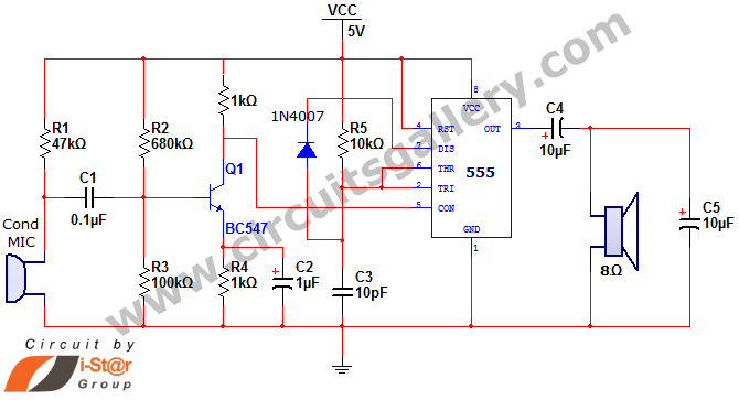
This document discusses a simple project utilizing the 555 timer IC. The 555 timer IC can be configured as an audio amplifier using an astable multivibrator configuration. It performs pulse width modulation (PWM) on an audio signal. The current...
A small circuit designed for various time measurement applications. It features an audible sound signal from the buzzer BZ1 and has the capability to drive an external circuit through the optocoupler IC2, once the appropriate circuit is connected to...
This easy electronic buzzer circuit is built based on a timer that operates to generate frequency. The IC timer NE555 is used as an astable multivibrator operating at approximately 1 kHz, producing a sound when powered on. The sound...

A switched timer with equal make and equal space periods timing adjustable from over 6 minutes to 38 minutes. This timer circuit is similar to the 5 to 30 minute timer except that when switch S1 is closed, the...
I had a Basic Stamp project that needed to measure a nominal 12 volt battery, and I wanted a simple solution. This is the simplest I could come up with. The 555 timer will put out positive pulses. The...