
Long time delay

The 556 timer is a versatile integrated circuit that combines two timing elements, making it suitable for various timing applications. The operation of the 556 timer relies on the charging and discharging of an external capacitor connected to its timing pins. When configured in astable mode, the timer generates a continuous square wave output, with the frequency and duty cycle determined by the resistor and capacitor values.
For applications requiring extended timing intervals, the selection of capacitors becomes critical. High-quality capacitors with minimal leakage currents are essential to ensure accuracy and reliability over long durations. Typically, time delays can be extended by cascading two or more timer sections. The first section operates in an oscillatory mode, generating a pulse train at a frequency of fo. This pulse train is then processed through a "Divide-by-N" network, which effectively reduces the frequency by a factor of N, resulting in a longer period output signal.
The output from the "Divide-by-N" network serves as the trigger for the second section of the 556 timer. This cascading approach allows for substantial increases in timing capabilities, as the total time delay is now a function of both the division factor N and the original frequency fo. By adjusting the resistors and capacitors in the circuit, designers can customize the timing characteristics to meet specific application requirements, thus enhancing the flexibility and functionality of the 556 timer in various electronic projects.In the 556 timer, the timing is a function of the charging rate of the external capacitor. For long time delays, expensive capacitors with extremely low leakage are required. The practicality of the components involved limits the time between pulses to something in the neighborhood of 10 minutes. To achieve longer time periods, both halves of a dual timer may be connected in tandem with a "Divide-by"" network in between the first timer section operates in an oscillatory mode with a period of 1/fo
This signal is then applied to a "Divide-by-N" network to give an output with the period of N/fo. This can then be used to trigger the second half of the 556. The total time delay is now a function of N and fo.
Related Circuits

This time delay switch circuit is designed to activate an AC load, such as lamps, after a delay of three minutes. It helps protect the load from inrush currents and transients during power-on, which can potentially harm the device....
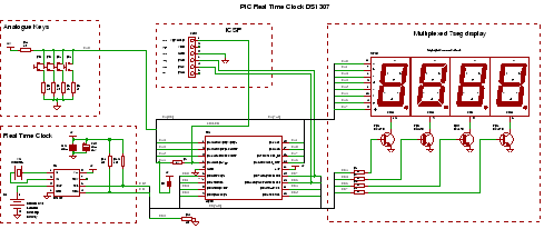
PIC RTC: A Real Time Clock IC using the DS1307 and a PIC microcontroller. This PIC project utilizes an I2C Real Time Clock chip and a display to create a four-digit standard desk clock. The described project incorporates a DS1307...
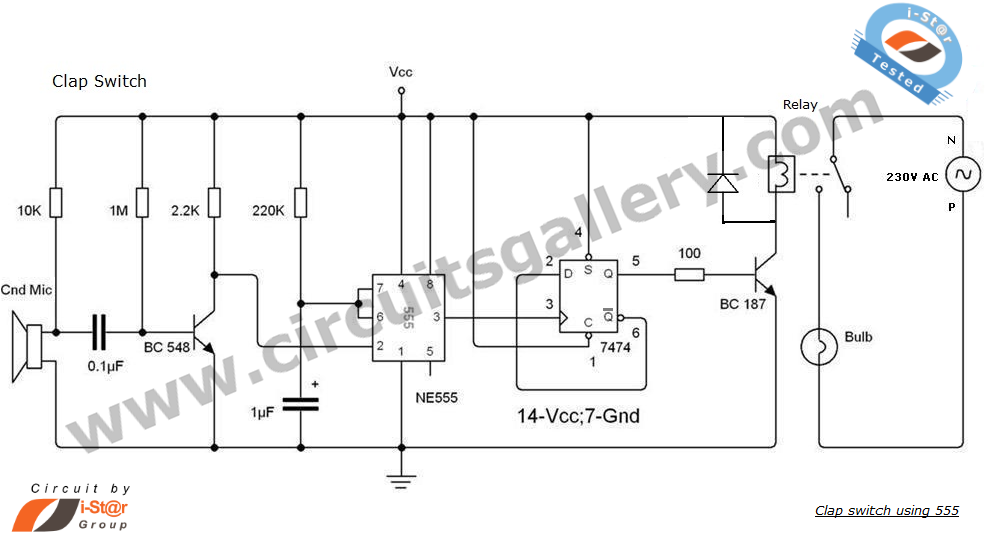
This is an intriguing 555 timer circuit designed to entertain and engage individuals while studying electronics in educational settings. Commonly referred to as a clap switch circuit, it operates as a sound-controlled flip-flop. This sound-controlled light can also function...
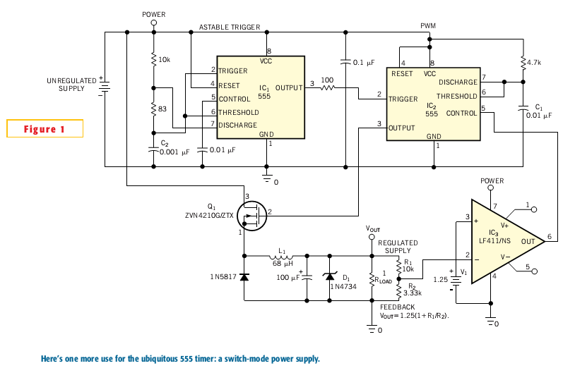
Most switch-mode power supplies utilize a PWM (pulse-width-modulated) output that is regulated through voltage feedback. A 555-timer IC can be used to generate PWM at a low cost. The circuit diagram illustrates how to convert a 555 PWM circuit...
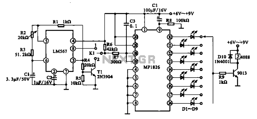
A precision circuit utilizing the LM567 timer, specifically the MPI826, where the LM567 functions as a dual-band oscillator. The MP1826 serves as a divider in the circuit, allowing the output signal from the LM567 to achieve extended timing. The...
The UBA2021 can be utilized as a 600 V lamp controller and half-bridge driver integrated circuit (IC) for high-power applications. It is designed for long-life compact fluorescent lamp (CFL) and tubular fluorescent lamp (TL) applications. The UBA2021 is a versatile...