
Record audio with the MSP430 microcontroller

The schematic for this project includes an electret microphone connected to the non-inverting input of the op-amp. The op-amp is configured as a non-inverting amplifier, with appropriate feedback and gain resistors selected based on the desired amplification level. The output of the op-amp is connected to the ADC input of the MSP430, ensuring that the signal is within the acceptable voltage range for the ADC. The low-pass filter is implemented between the op-amp output and the ADC input to eliminate high-frequency noise, enhancing the quality of the audio signal being sampled. The power supply connections for the op-amp and the MSP430 are established to ensure proper operation, with decoupling capacitors placed near the power pins to stabilize the voltage levels. Additionally, the schematic should reflect the necessary connections for the external voltage reference, ensuring that the F2013 can operate effectively with the chosen reference voltage. Proper grounding practices should be followed throughout the circuit to minimize noise and interference. Overall, the design aims to provide a reliable method for capturing audio signals using a low-cost electret microphone and processing them with the MSP430 microcontroller.This project uses a small, common electret microphone to convert audio to an electrical signal. These are the cheap microphones found in most PC headsets. The microphone output must be amplified and zeroed before it can be recorded with the MSP430. This is done with an operational amplifier, or op-amp. The op-amp amplifies the tiny, oddly centere d audio signal into a full range signal based on 0 volts. The diagram shows the original signal (blue) and the amplified, full range signal outputted by the op-amp (red). I`m not much of an analog designer, so may I refer you to any of these tutorials on op-amps if you need more info: wikipedia, a flash tutorial, opamp basics.
The op-amp design I used came directly from TI`s digital audio recorder application note slaa123 [pdf!] (page 3). TI`s design uses a TI TLV2252 dual op-amp. We only need one, so I substituted a single channel TI TLV2221 op-amp. I used the circuit and values from the TI app note, but substituted the 2K/. 01uf low-pass audio filter I chose in part II. The TLV2221 is only available in a surface mount package. If you want to do an all through-hole version of this project, consider a TLV2252 based design. We`ll use the MSP430`s on-chip analog-to-digital converter (ADC) to measure the audio signal. The ADC is a pin that measures analog voltages. Measurements taken by the ADC are recorded as a fraction of a voltage reference (Vref). In the prototype, the voltage reference will equal that of the circuit - 3. 3 volts. The smallest voltage change that can be measured by the ADC is denoted in bits. An 8 bit ADC measures voltage on a scale of 0 to 255. A reading of 127 (127/255=50%) from the ADC represents ~1. 65 volts (0. 50 * 3. 3 volt reference). The diagram shows the relationship between bits, voltage reference, and measurements taken by the ADC.
The MSP430F2012 has a 10 bit (0-1024) ADC, while the F2013 has a higher-resolution 16 bit (0-65535) ADC. The higher resolution ADC could, in theory, be used to capture better audio. The prototype design is unproven and bound to have problems. Here`s a big one! Most ADCs, including the Microchip PIC, ATMEL AVRs, and even the MSP430F2012, can use the circuit power supply as the ADC voltage reference.
An internal switch, manipulated from software, determines the reference source. I planned to use this feature to measure the op-amp output, which is scaled to the 3. 3 volts used in the circuit. The F2013, despite my assumptions, does not appear to have an internal Vref connection to the chip power supply. The F2013`s internal Vref comes from a precision 1. 2 volt reference. An external voltage reference can be sourced through pin 5 (P1. 3), where a LED currently connects. Future designs should take this limitation into account, and connect the F2013 Vref pin directly to the power supply.
My work-around was to remove the LED and solder a fly-wire from the power pin to the Vref pin. An external Vref is used if SD16REFON and SD16VMIDON are both cleared to 0, according to page 24-4 of the MSP430F2xxx Family User`s Guide [pdf!]. This didn`t work for me. Eventually, I messed around enough to destroy the MSP430. In desperate need of a break, I removed the dead MSP430F2013 and replaced it with a F2012. The F2012 has only 10 bits of ADC resolution, but is able to use the chip supply as a voltage reference.
The example program samples audio from the microphone and puts it immediately in the PWM duty cycle register. The result is a useless "middle man" that echoes everything heard by the microphone. This project is based on the firmware from my last article. A timer triggers an alarm (an interrupt) 8000 times per second. An ADC measurement is started each time the alarm sounds. The ADC measurement isn`t ready immediately - it takes a few cycles for the conversion to be readable.
We don`t need to worry about this period, because the ADC will trigger it`s own interrupt when the measu 🔗 External reference
Related Circuits
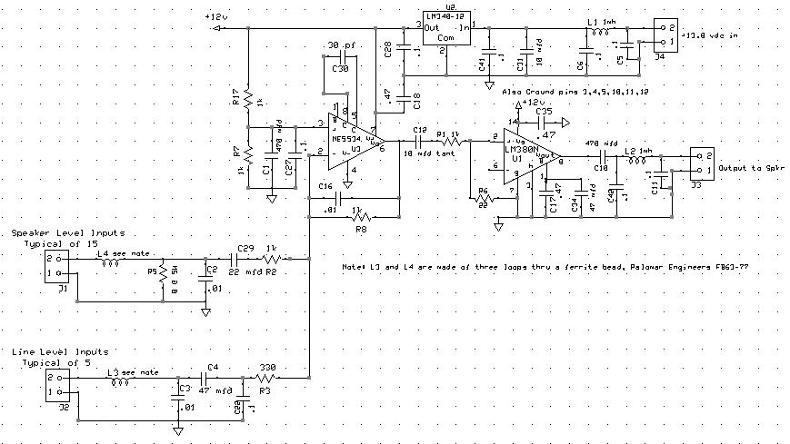
The audio mixer allows for easy comparison of various receivers by adjusting the gain controls without the need for switching. This setup simplifies A/B comparisons since all receivers are connected to the same antenna. Previously, different speakers were used...
A USB solution is required for a project utilizing the LPC2148 microcontroller (MCU). In the past, interfaces such as LPT or COM were commonly used to connect projects to a PC, but these have become obsolete. The project allows...
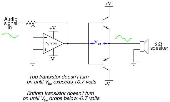
The closer the two transistors are matched, the better the performance. It is advisable to use TIP41 and TIP42 transistors, which are closely matched NPN and PNP power transistors with a dissipation rating of 65 watts each. If a...
This document discusses the advantages and disadvantages of various power supply technologies, along with the design considerations necessary for selecting and evaluating a mains transformer. It covers the pros and cons of external supplies, inrush current control, RF emissions...
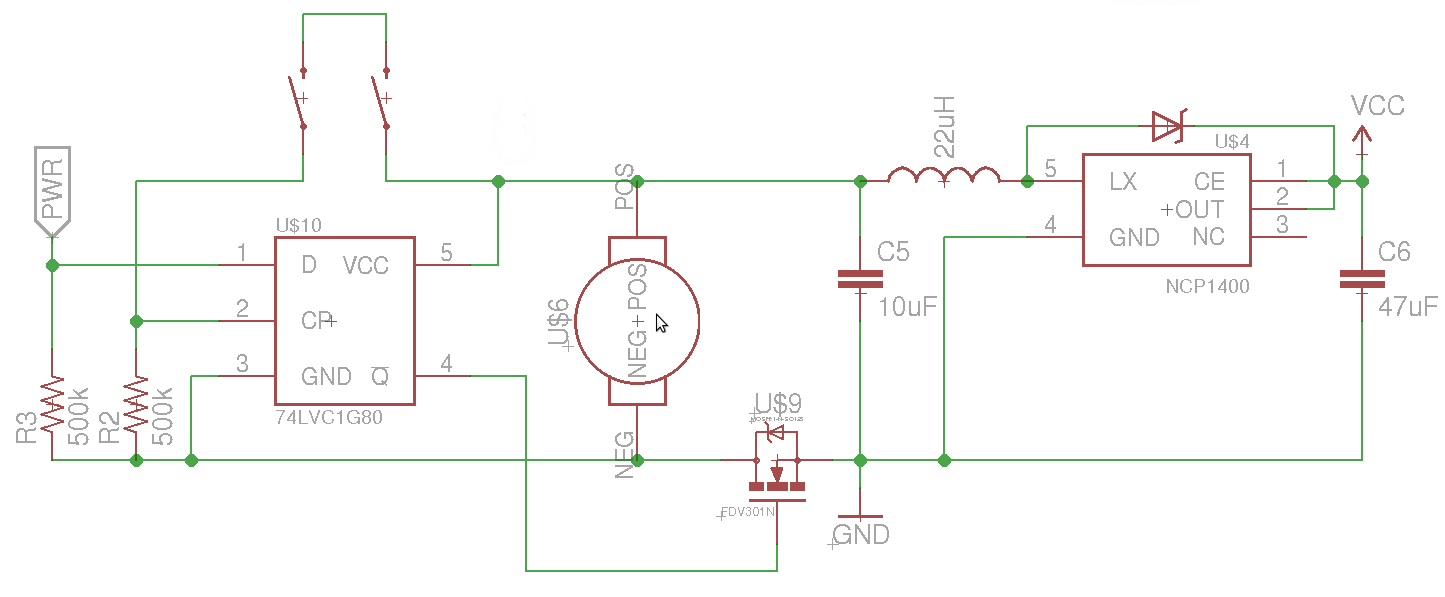
The objective is to control the power to a load, specifically an 8051-based microcontroller (uC), using two switches. When the uC is powered on, it sets the PWR pin high. Upon pressing the switches again, pin 4 of the...
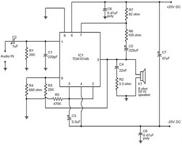
This document provides a circuit diagram of a car stereo. It includes a circuit diagram of a Class B 15 Watts audio amplifier designed using a dual op-amp and a transistor. The 15 W Class B audio amplifier circuit...