
Loop-stick Antenna for AM band

The loopstick antenna described utilizes a three-foot length of PVC pipe as its core, upon which approximately 500 turns of #24 copper wire are wound. This design allows for a compact antenna solution that enhances AM radio reception without the need for a long wire or ground connection. The inductance of this configuration is calculated using the formula for a single-layer air-core inductor, which is dependent on the radius of the coil, the number of turns, and the length of the coil. The target inductance for optimal performance with a standard AM radio tuning capacitor, which ranges from 33 to 330 pF, is approximately 230 microhenries.
The primary coil, formed by the initial 500 turns, results in an inductance value that may vary slightly due to the spacing of the windings. In this case, the final inductance measured was around 213 microhenries. Additionally, a secondary coil consisting of approximately 50 turns is wound on top of the primary coil. This secondary coil is strategically connected to four turns of wire that are wound around the radio, ensuring that the internal antenna rod of the radio passes through the external windings. This configuration enhances the coupling between the antenna and the radio.
For optimal performance, the antenna must be oriented horizontally and positioned at right angles to the direction of the desired radio station. The tuning process involves adjusting the radio to a weak station and carefully tuning the antenna capacitor while also rotating the antenna to achieve the best reception. It is crucial to position the antenna away from sources of electrical interference, such as lamp dimmers and computer monitors, to prevent degradation of the signal quality. Overall, this loopstick antenna design provides an effective means of improving AM radio reception, particularly for distant stations.Wound on a 3 foot length of PVC pipe, the long loopstick antenna was an experiment to try to improve AM radio reception without using a long wire or ground. It works fairly well and greatly improved reception of a weak station 130 miles away. A longer rod antenna will probably work better if space allows. The number of turns of wire needed for the loopstick can be worked out from the single layer, air core inductance formula: Inductance = (radius^2 * turns^2) / ((9*radius)+(10*length)) where dimensions are in inches and inductance is in microhenrys.
The inductance should be about 230 microhenrys to operate with a standard AM radio tuning capacitor (33-330 pF). The 3 foot PVC pipe is wound with approximately 500 evenly spaced turns of #24 copper wire which forms an inductor of about 170 microhenrys, but I ended up with a little more (213uH) because the winding spacing wasn't exactly even. A secondary coil of about 50 turns is wound along the length of the pipe on top of the primary and then connected to 4 turns of wire wound directly around the radio.
The windings around the radio are orientated so that the radio's internal antenna rod passes through the external windings. A better method of coupling would be to wind a few turns directly around the internal rod antenna inside the radio itself, but you would have to open the radio to do that.
In operation, the antenna should be horizontal to the ground and at right angles to the direction of the radio station of interest. Tune the radio to a weak station so you can hear a definite amount of noise, and then tune the antenna capacitor and rotate the antenna for the best response.
The antenna should also be located away from lamp dimmers, computer monitors and other devices that cause electrical interference. 🔗 External reference
Related Circuits
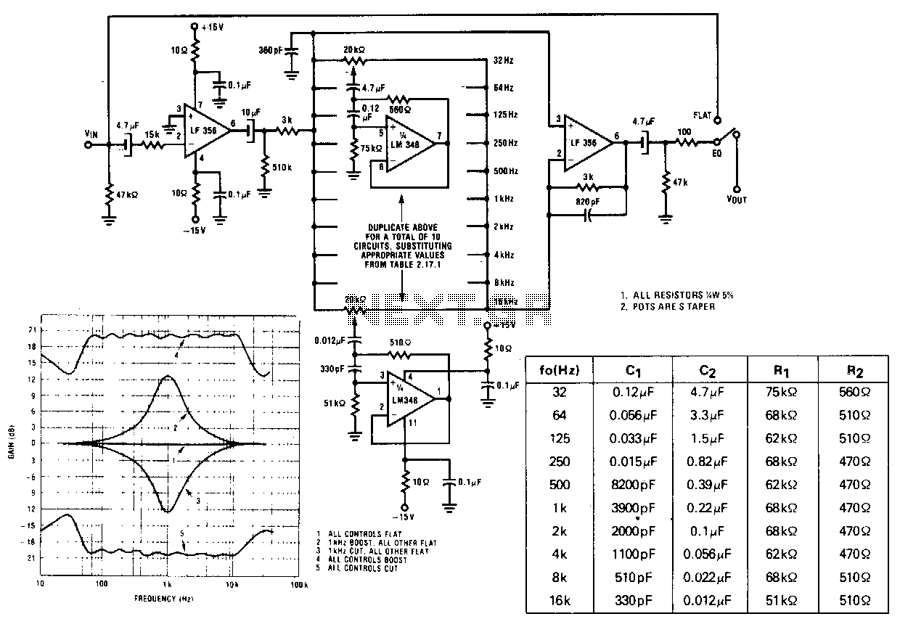
A series of active RF filters using the National LM3481C comprises a ten-band graphic equalizer. C1, C2, R1, and R2 should be at least 10% with 5% preferred tolerances. The circuit design features a ten-band graphic equalizer that utilizes a...
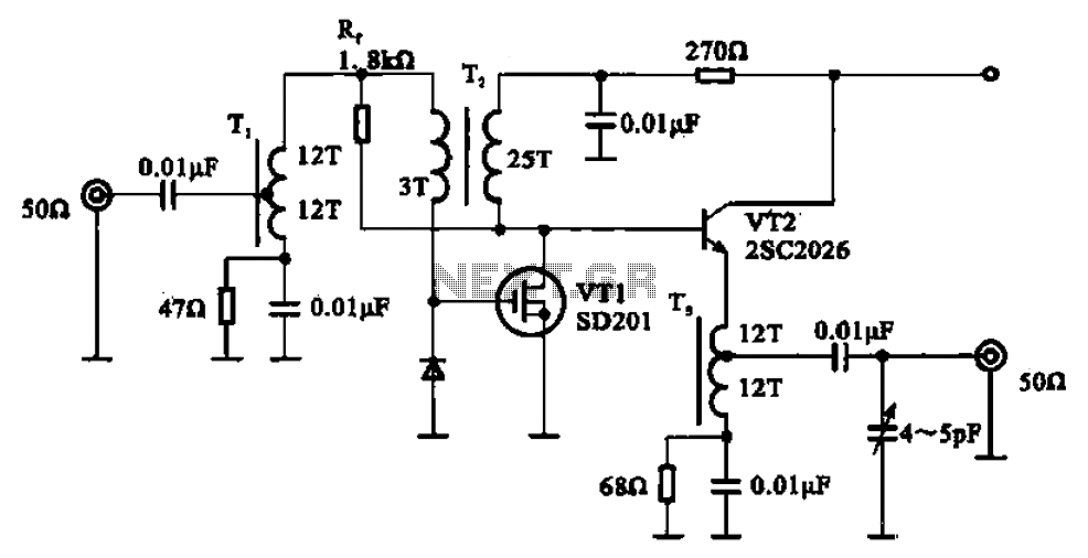
A broadband amplifier circuit utilizing a negative feedback amplifier configuration is presented. This circuit employs transformer coupling and a combination of amplifying sections and field-effect transistors (FETs). The input signal is applied to the center tap of the transformer...
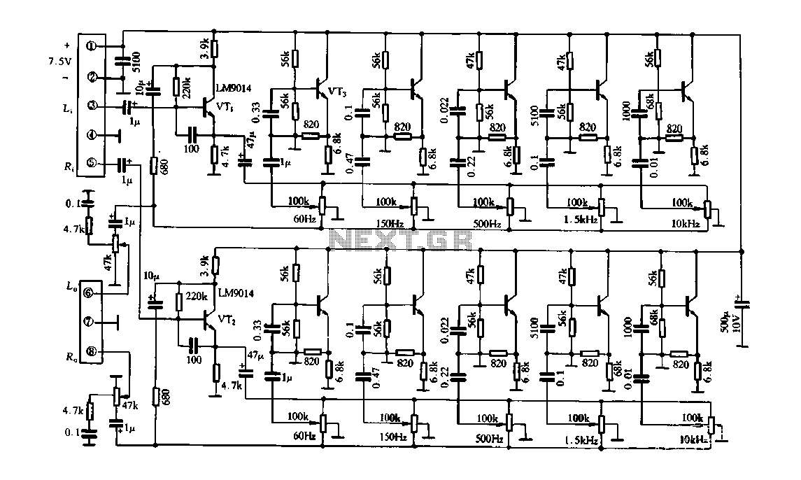
Figure 4-33 illustrates a circuit configuration that includes a common amplifier along with analog inductive circuits. In this setup, the transistor in the analog inductive circuit is utilized, and an increase in the bias resistor enhances circuit stability. A...
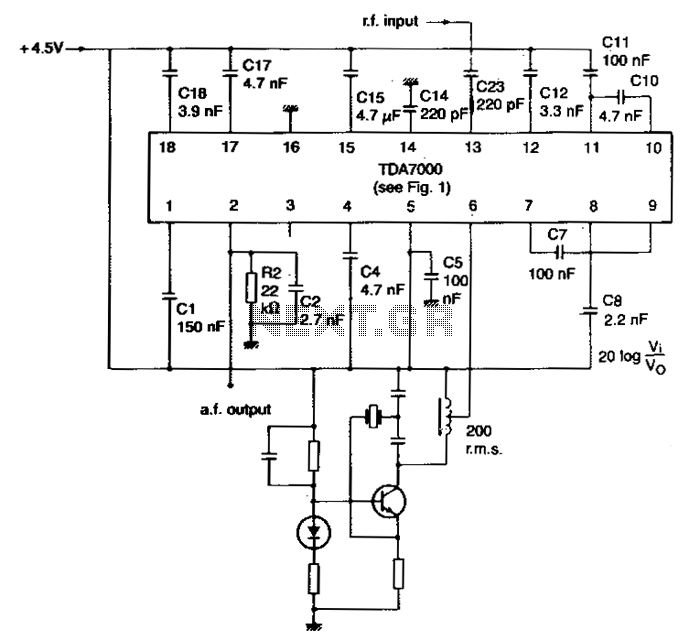
The local oscillator is controlled by a crystal, and the intermediate frequency (i-f) swing is minimally compressed. To prevent significant distortion of the demodulated audio signal, the deviation of the transmitted carrier frequency due to modulation must be limited....
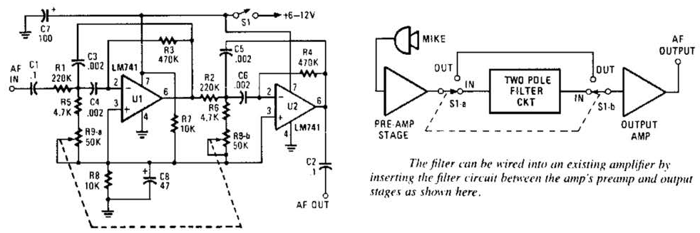
This variable-frequency audio bandpass filter is constructed using two 741 operational amplifiers connected in cascade. The two 741 op amps are configured as identical RC active filters and are cascaded to enhance selectivity. The filter's tuning range spans from...
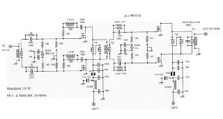
This is an RF Power Amplifier designed for low-cost QRP applications. The circuit operates over a broadband frequency range of 1.8 to 30 MHz, eliminating the need for tuning. The only adjustment required is to set the quiescent current...