
Loudspeaker Protection

The described detector circuit is designed to effectively identify and respond to DC offsets while maintaining immunity to low-frequency signals and asymmetrical waveforms. The circuit's operation is characterized by its ability to remain inactive when subjected to a 30V RMS signal at a frequency of 5Hz, indicating a robust filtering mechanism that prevents false triggering from low-frequency AC signals.
Upon application of a DC voltage, the circuit demonstrates a response time of 60 milliseconds when a 30V DC supply is used, and a slightly faster response of 50 milliseconds with a 45V DC supply. This rapid response is crucial for applications requiring timely detection of DC offsets. The use of a non-polarised electrolytic capacitor in the filter design is particularly advantageous, as it allows for cost-effective and compact circuit solutions. These capacitors are well-suited for this application due to their small size and adequate performance in filtering tasks.
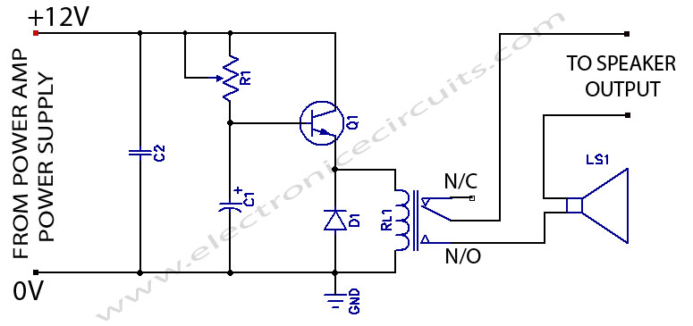
The primary function of the circuit is to detect DC offsets of both polarities, ensuring versatility in various applications. The design aims to eliminate sensitivity to asymmetrical waveforms, which is a common challenge in signal detection circuits. This capability is essential for reliable operation in environments where signal integrity may be compromised by noise or distortion. The simplicity of the circuit design enhances its reliability and ease of implementation, making it an ideal choice for a variety of electronic applications that demand efficient DC detection without the complications introduced by complex circuitry.The detector circuit shown in Figure 1 (1) is simple and works well, and as shown will not trigger with a 30V RMS signal at 5Hz, but operates in 60ms with 30V DC applied, and in 50mS with a 45V DC supply. This should be sufficient for most applications, and allows the use of a non-polarised electrolytic capacitor in the filter.
These are cheap, small and quite adequate for this purpose. This is the most important of the functions. It must be capable of detecting a DC offset of either polarity, and be immune to the effects of asymmetrical waveforms and low frequencies. This is a common requirement, and it is most expedient to use a simple 🔗 External reference
Related Circuits
When powering on a power amplifier, a loud thump sound occurs due to a sudden heavy discharge current through the speaker. This current has the potential to damage the speaker, particularly in the case of a direct-coupled amplifier. The phenomenon...
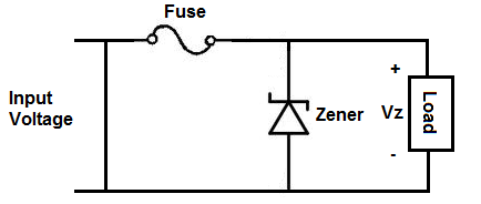
An overvoltage protection circuit is designed to safeguard electronic components from excessive voltage that could potentially cause damage or destruction. This project involves constructing a straightforward yet effective overvoltage protection circuit using a fuse and a zener diode as...
All optical transmitters will include circuitry designed to limit the current to a safe value that protects the LED during short-term incidents. Red, Red-Orange, and Amber Luxeon I LEDs have a peak current rating of approximately 550 mA. At...
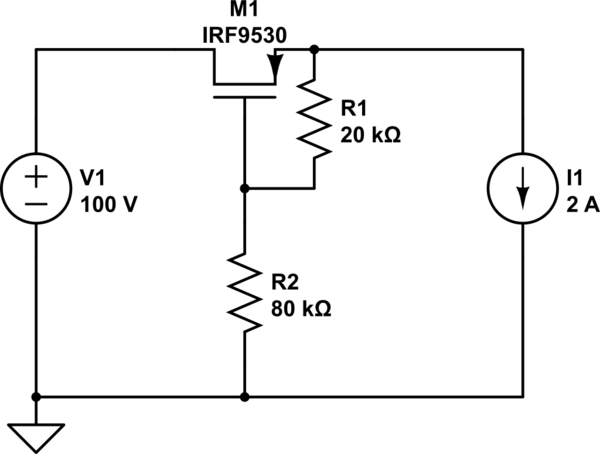
When a reverse voltage of 10V is applied to the source while the drain is grounded, the gate-source voltage (Vgs) becomes -10V. This voltage is significantly above the threshold, which allows the MOSFET to remain in the saturation region,...
This scheme is a Standing Wave Ratio (SWR) meter, which is relatively simple and can be easily constructed. Once a directional coupler is created, the results will be indicated on the measuring LED meters as a ratio of SWR. The...
Figure 4-27 (b) line demonstrates a configuration that enhances the output current waveform DC voltage compared to the line in Figure 4-27 (a). This configuration can be utilized for motors with larger capacities. The circuit illustrated in Figure 4-27 (b)...