
SWR Protection Circuit

The SWR meter is an essential tool in RF (radio frequency) applications, used to measure the standing wave ratio of a transmission line. The SWR meter typically consists of a directional coupler, which samples the forward and reflected power in the transmission line. The directional coupler is usually constructed using a series of resistors and inductors that create a voltage divider, allowing for the measurement of both forward and reflected signals.
In operation, the SWR meter takes the voltage readings from the directional coupler and processes them to determine the SWR value. The SWR is calculated using the formula: SWR = (1 + |Γ|) / (1 - |Γ|), where |Γ| is the reflection coefficient derived from the measured voltages. The resulting SWR value is then displayed on LED meters, providing a visual representation of the efficiency of the antenna system.
To build the SWR meter, one must first design the directional coupler, ensuring that it can handle the expected power levels without distortion. The coupler should be calibrated to provide accurate readings across the frequency range of interest. Additionally, the LED meters should be selected based on their sensitivity and response time to ensure they accurately reflect the SWR in real-time.
Overall, the SWR meter is a straightforward yet effective device for monitoring antenna performance, helping to optimize transmission efficiency and minimize signal loss. Proper construction and calibration are key to ensuring accurate measurements, making it a valuable asset for amateur radio operators and professionals alike.This scheme is an SWR meter, which is quite simple and easily built. Once you make a directional coupler, the results will be displayed with the measure led meters as a ratio SWR. 🔗 External reference
Related Circuits
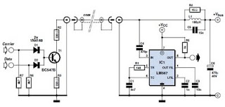
This circuit was designed to transmit commands over an LNB coaxial cable. An LNB (Low-Noise Block downconverter) is commonly used for satellite TV reception and is positioned at the focal point of a satellite dish. The circuit generates a...
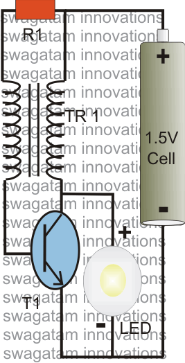
The post explains a simple 1 watt LED driver circuit using a single 1.5 V penlight cell through the joule thief concept. The coil may be wound over a T13 toroidal ferrite core using 0.2 mm or 0.3 mm...
This is a beta release schematic. Use at your own risk. The idea is to add this circuitry to a board that already has RAM at address 2000 and an 82C55 I/O chip to provide ports A, B, and...

A magnetic switch is a circuit designed to respond to surrounding magnetic fields detected by the sensor. This series of magnetic switches employs limit switch sensors that include an additional metal plate capable of responding to a magnet. The...
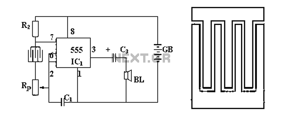
Figure 1 illustrates a circuit diagram related to an audio circuit that incorporates a resistance between two leads connected to a rain alarm probe. Figure 2 demonstrates the connection of a capacitor to the probe within the audio circuit....
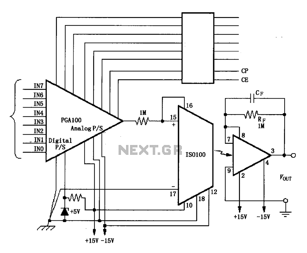
The ISO100 multichannel data acquisition system comprises a programmable gain amplifier isolated by an optocoupler, a programmable amplifier (PGA100), and an isolation amplifier (ISO100). The optocoupler selects three channels and is coupled to the programmable gain amplifier, which can...