
Loudspeaker Protection circuit

The protection circuit is designed to safeguard audio amplifiers and speakers from potentially damaging conditions. It employs a combination of analog components such as comparators, transistors, and relays to ensure safe operation. The circuit operates by isolating the speaker from the amplifier output when specific conditions are detected, including continuous output trends or excessive temperature drops.
At the core of the circuit is a binary comparator (IC1) that monitors the operational state of the amplifier. The power supply is stabilized at +15 V using a Zener diode (D3) and a resistor (R17). The circuit is activated by closing the AC power switch, which allows an alternating voltage to appear at terminal B. This voltage is rectified by diode D2, providing a negative voltage that controls transistor Q3, effectively charging capacitor C4 through resistors R10 and R11.
As C4 charges, the voltage at the input of comparator IC2B remains low until a sufficient charge is reached, at which point the output of IC2B transitions to a high state, activating relay RL1 and connecting the speakers to the amplifier while turning off LED D6. This delay mechanism prevents the speakers from being exposed to transient noise during power-up.
In the event of an amplifier output issue, transistors Q1 and Q2 act to deactivate relay RL1, thereby disconnecting the speakers and preventing damage. The audio signal from the amplifier is monitored at point D, where fluctuations in the signal voltage are filtered through capacitors C1 and C2. If the signal voltage exceeds predetermined thresholds, the corresponding transistor is activated, which further influences the state of relay RL1.
Thermal protection is integrated into the design via a positive temperature coefficient (PTC) thermistor (RTH), which is mounted on the heatsink. As temperatures rise, the resistance of RTH increases, affecting the input levels of comparator IC1A. If the temperature exceeds 70 °C, the output of IC1A switches low, triggering a protective response that deactivates relay RL1 and illuminates LED D5 to indicate thermal protection activation.
Overall, this protection circuit is a comprehensive solution to ensure the safe operation of audio amplifiers and speakers, effectively mitigating risks associated with output anomalies and thermal overloads.The protection circuit output amplifiers and speakers, has some interesting features such as isolating the speaker from the amplifier output when shown a continuous trend in output or when the temperature gets too much cooler while providing a time delay and the connection of the speaker amplifier, to avoid passing them, the known irritating noise from the charge-discharge power supply capacitors. It consists of a binary comparator [IC1], transistors Q1-2 and indicative LED D5-6. The power circuit can be made from the positive trend [point A] to the main power supply, which is stabilized by the D3 and R17, at +15 V.
Point B is connected to one of the secondary AC power adapter. Just close the power switch AC, then an alternating voltage appears on terminal B, is rectified by D2 and supplies a negative voltage through R9, in Q3, it cuts off and begins to charge the C4 through R10-11. So long as the duration of the load capacitor, the input [+] IC2B the comparator is at a low level compared to the input [-].
The output of IC2B, has a low level, so that Q4 remains off and remains off RL1, the D6 is on. Once the C4 charge, the state changes IC1V activates the RL1, the speakers connected to the amplifier, the D6 off. When power is interrupted throughout the process is reversed, and the speakers disconnected, without going through annoying noises.
If the circuit works as a problem occurs at the output voltage of the amplifier, it's a relaxation of RL1 and protect the speakers. This is done with the help of Q1-2. The audio signal from the output of the amplifier leads to point D, the changing trends led to earth via the C1-2, generating a non-polar capacitor.
Ongoing trends, greater than +1.7 V or below?? 4.8V, directly activate the Q1 or Q2, respectively. By enabling transistor lowered the level of [+] input IC1B, thereby apodiegeiretai and RL1. Another area that gives us protection circuit is thermally protected. This is done by using a sensor temperature of RTH, which is a resistance type PTC (positive temperature coefficient), and is mounted onto the heatsink, where they are and the power transistors. The price increases with increasing temperature, until the dynamic entry [-] of IC1A, rises above the level of input [+] determined by the voltage divider R2-3.
Once the entry level [-] exceeds the level of entry [+], the output of IC1A, switched to a low level, forcing IC2B and changing situation, apodiegerthei the RL1 and turn on the D5, which shows the heat protection. In the circuit the threshold above which there is evidence of thermal protection are 70? C. If there is instability at this stage in the operation of RL1, should be changed to R4, with another smaller.
R1-2=27 Kohms R13=1.5 Kohms Q1-2-3=BC337 R3=1.4 Kohms R15=4.7 Kohms Q4=BC639 R4=1 Mohms R16=33 Kohms D1=1N4148 R5-14-17=3.3 Kohms R18=1.5 Kohms 5W D2=1N4004 R6-7=100 Kohms RTH=KTY81-122 D3=15V 1.5W Zener R8=47 Kohms C1-2=100uF 63V D4=1N4002 R9-11=120 Kohms C3=470nF 100V MKT D5-6=LED R10=470 Kohms C4-5=47uF 25V RL1=24V Relay R12=15 Kohms IC1=LM393 🔗 External reference
Related Circuits
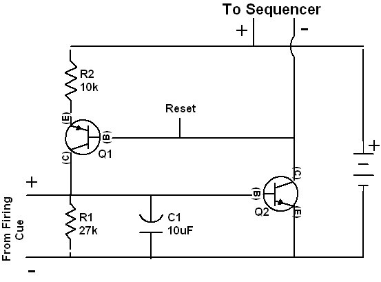
The 4017 integrated circuits are not initialized to a known state because the reset pins are not briefly forced high when the circuit is powered on. While the chips might typically power up in the normal reset condition, this...
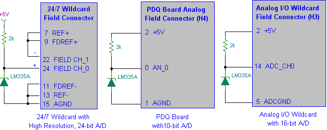
Interfacing the LM335A temperature sensor with A/D converters involves measuring temperature using the LM35 and LM335A sensors alongside the 9S12 HCS12 microcontroller. This process includes analyzing both calibrated and uncalibrated temperature errors of integrated circuit temperature sensors. The LM335A is...
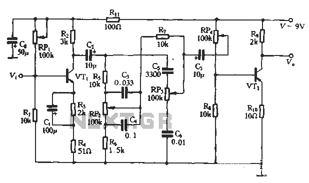
This article presents a diagram of an attenuated tone control circuit. The circuit primarily consists of transistors and RC networks as its components. The circuit operates in such a way that the shunt effect of capacitor C4 and resistor...
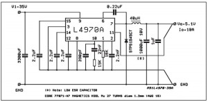
A small-sized and easy-to-build 5V 10A power supply circuit is being sought. This circuit utilizes the L4970A integrated circuit as a 10A switching regulator. It is essential that the power supply input can handle a current of 10A to...

This circuit diagram represents a logic probe based on a single CMOS integrated circuit (IC). The logic probe indicates three conditions: High, Low, and Pulsing. Additionally, no LEDs will illuminate when the probe input is in a high-impedance state,...
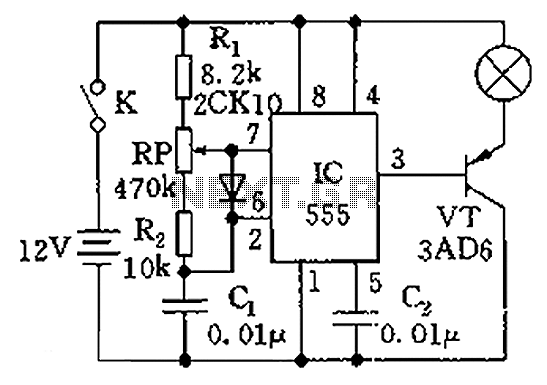
The circuit illustrated in the figure is a dimmer using the 555 timer as the core component. The 555 timer, along with resistors R1, RP, R2, and capacitor C1, forms an astable multivibrator. The oscillation frequency, f, is calculated...