
Loudspeaker Protector Circuit

The circuit employs transistors Q1, Q2, and Q3 for monitoring the output offsets of the stereo amplifier, ensuring that any deviation beyond 2 V triggers a protective response. When the output offsets exceed the specified threshold, Q7 is deactivated. This action leads to the deactivation of Q8, which is connected to a relay that is normally energized. The relay's function is to disconnect the loudspeakers from the amplifier to prevent potential damage from excessive voltage offsets.
Diodes D2 and D5, in conjunction with Q4, act as a mains voltage monitoring system. Their role is critical in detecting the presence of AC voltage. When the amplifier is powered down, the AC input voltage drops, causing Q4 to turn off. This transition activates Q5, which is designed to maintain the protective state by turning off Q7 and Q8, thereby ensuring the relay is also deactivated.
The design emphasizes safety and protection for the loudspeakers, ensuring they are disconnected promptly in the event of power loss or significant output offset. This circuit configuration is vital in maintaining the integrity of audio equipment and preventing damage during operation and shutdown scenarios. Transistors Ql, Q2, and Q3 monitor the two outputs of the stereo amplifier. If the offsets exceed 2 V, Q7 is turned off, which turns off Q8 and the normally on relay. Diodes D2 and D5, together with Q4, provide a mains voltage monitor. As soon as the ac input voltage disappears, as when the amplifier is turned off, Q4 turns off arid Q5 turns on. This turns off Q7, Q8, and the relay. Hence, the loudspeakers axe disconnected immediately after the amplifier is turned off.
Related Circuits

This is a simple smoke alarm circuit using a timer IC, the NE555. The circuit operates by illuminating a Light Dependent Resistor (LDR) with a lamp. When smoke obscures the light from the lamp, the resistance of the LDR...
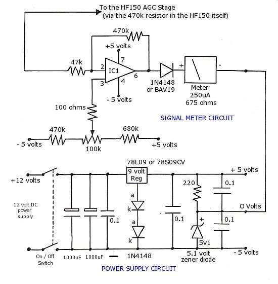
The operational amplifier (op-amp) used in the signal meter circuit is the TL061. The LF351 can also be used interchangeably, as it has the same pin layout. For those using a TL062 or similar models, the differing pin configurations...
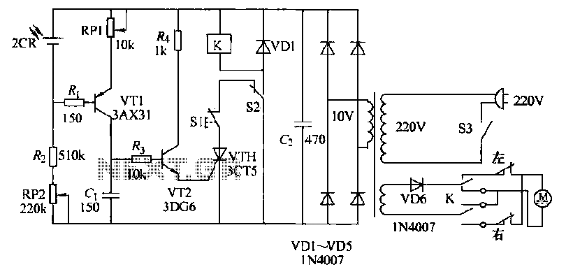
The circuit operates as follows: each morning, light enters the silicon photocell, generating a force that causes transistor VT1 to conduct. As a result, capacitor C charges, leading to an increase in voltage. This rising voltage causes the emitter...
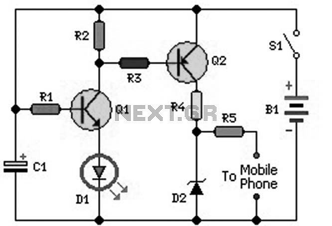
An ideal mobile charger utilizing 1.5-volt pen cells to charge mobile phones while traveling. This charger can replenish a cell phone battery three to four times in locations where AC power is unavailable. Most mobile phone batteries are rated...
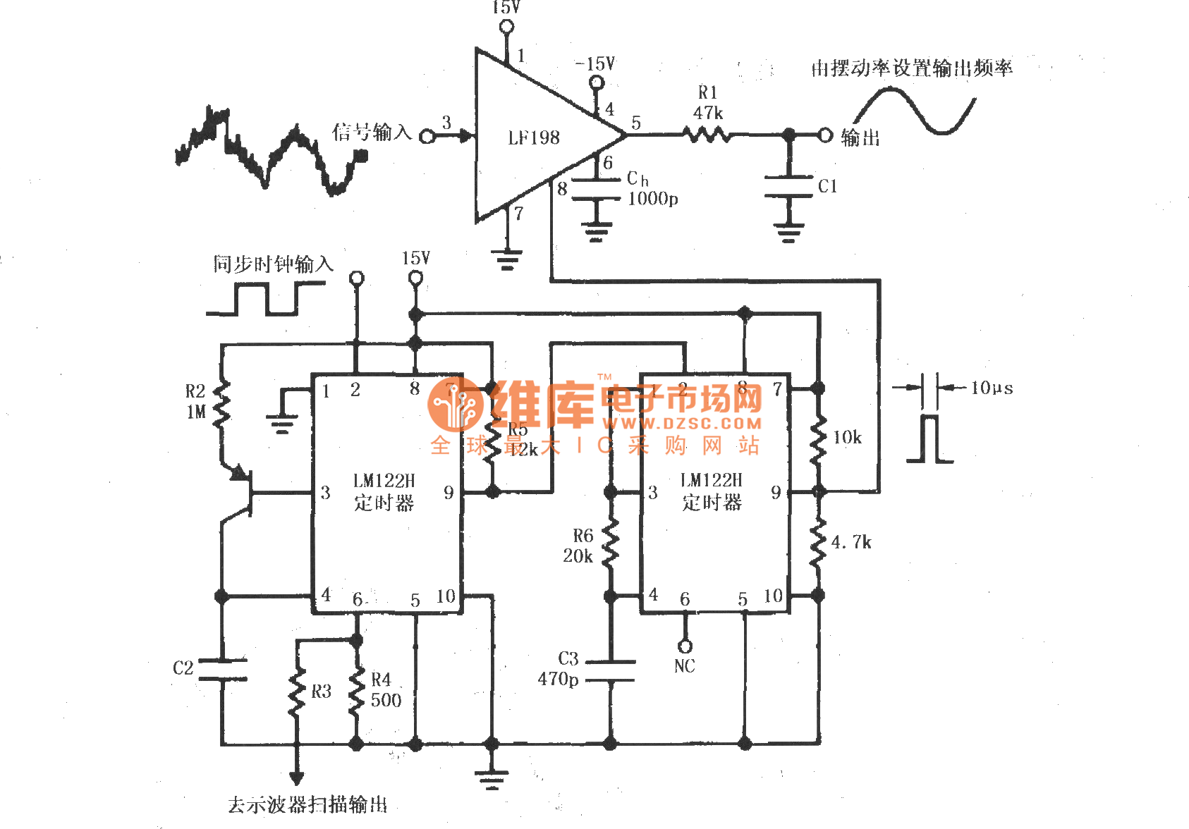
A synchronous clock signal is fed into a cascade of timer circuits composed of two LM122H devices. The synchronization clock is then converted into a pulse of the desired width, which is added to the LF198 logic end (pin...
The main ΣΔ loop operates in steady state and is fully controlled by summing comparator Q2. This comparator amplifies the ripples of the sensed inductor current and output voltage with gains KI and KV, respectively, to generate an internal...