
Simple fire alarm circuit using IC timer NE555

This smoke alarm circuit utilizes the NE555 timer IC in an astable configuration, producing a continuous square wave output that can be used to drive an audio alarm. The LDR acts as a light sensor, and its resistance decreases when exposed to light, allowing for a threshold detection of smoke that obscures this light. The interaction between the LDR and the thermistor is crucial for the operation; when smoke is detected, the change in resistance triggers the alarm system.
The design incorporates transistors for signal amplification and switching. Transistor T1 (BC548) is responsible for amplifying the signal from the thermistor, while T2 serves to reset the NE555 timer, ensuring that the alarm remains inactive in normal conditions. The output from the NE555 is used to drive T3 (SL100), which in turn activates the speaker to emit an alarm sound, alerting users to the presence of smoke.
The choice of resistors R5 and R6, along with the capacitor C2, determines the frequency of the oscillation produced by the NE555, which is typically set within the audio range to ensure the alarm is audible. The capacitor C1 plays a critical role in timing; it determines how long the alarm will sound once triggered. The use of diode D1 is essential for maintaining the charge in C1, preventing it from discharging prematurely and ensuring that the alarm remains activated until the smoke condition is resolved.
Overall, this circuit is a practical application of the NE555 timer and demonstrates the integration of various electronic components to create a functional smoke detection and alarm system. Proper selection of component values and careful design considerations ensure reliable operation in detecting smoke and providing timely alerts.Here the simple file alarm circuit based timer ID NE555. The works is simple, the lamp give light to the LDR (Light Depending Resistor) as light sensor. When the light from the lamp covered with smoke then the LDR will change its resistance value and then activated the alarm. The IC1 (NE555) is configured as a free running oscillator at audio freq uency. The transistors T1 and T2 drive IC1. The output(pin 3) of IC1 is couples to base of transistor T3(SL100), which drives the speaker to generate alarm sound. The frequency of NE555 depends on the values of resistances R5 and R6 and capacitance C2. When thermistor becomes hot, it gives a low-resistance path for the positive voltage to the base of transistor T1 through diode D1 and resistance R2.
Capacitor C1 charges up to the positive supply voltage and increases the the time for which the alarm is ON. The larger the value of C1, the larger the positive bias applied to the base of transistor T1 (BC548).
As the collector of T1 is coupled to the base of transistor T2, the transistor T2 provides a positive voltage to pin 4 (reset) of IC1 (NE555). Resistor R4 is selected s0 that NE555 keeps inactive in the absence of the positive voltage. Diode D1 stops discharging of capacitor C1 when the thermistor is in connection with the positive supply voltage cools out and provides a high resistance path.
It also inhibits the forward biasing of transistor T1. 🔗 External reference
Related Circuits
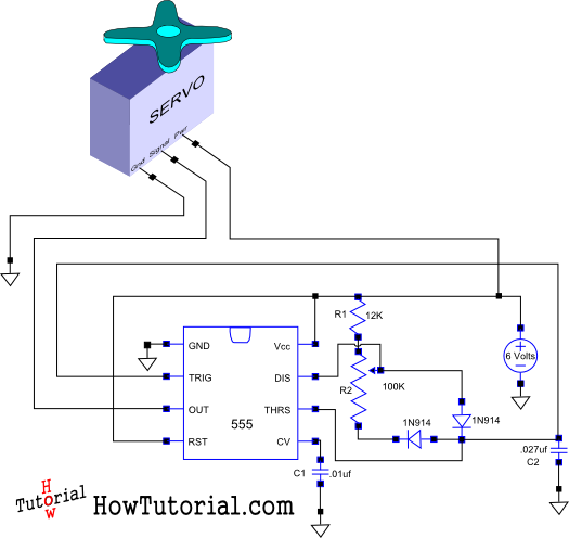
This document outlines the design of a simple circuit that enables control of a servo motor and allows for testing its functionality. The circuit for controlling a servo motor typically consists of a microcontroller, a power supply, and the servo...
The following circuit illustrates the sensor circuit of an analog line follower robot. Features include control by a microcontroller and a sensor circuit. The sensor circuit for an analog line follower robot is designed to detect the presence of a...
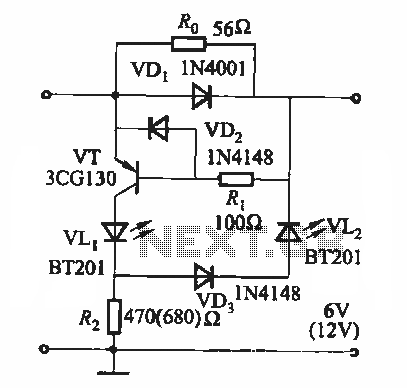
During the charging process, the green light-emitting diode (LED) VLi indicates that the battery is sufficiently charged, while the red light-emitting diode (LED) VLz illuminates when the battery is low. The circuit involves two light-emitting diodes (LEDs) serving as indicators...
This article compares high-side and low-side amplifiers used for measuring battery charging currents. It recommends selection criteria for current-sense resistors and describes a high-voltage circuit breaker designed for overcurrent protection. High-side and low-side amplifiers are essential components in battery management...

An FM and AM transmitter integrated into a compact device utilizing the CD4001 integrated circuit. It broadcasts at 20 MHz for AM and 100 MHz for FM. The described transmitter combines both Frequency Modulation (FM) and Amplitude Modulation (AM) capabilities...
This text continues the discussion on a Class D amplifier utilizing a 555 timer chip. In reviewing previous schematics, the inclusion of a second 555 timer (U2) raises questions. The primary function of U2 is to provide a constant...
Warning: include(partials/cookie-banner.php): Failed to open stream: Permission denied in /var/www/html/nextgr/view-circuit.php on line 713
Warning: include(): Failed opening 'partials/cookie-banner.php' for inclusion (include_path='.:/usr/share/php') in /var/www/html/nextgr/view-circuit.php on line 713