
Low-Consumption Monostable Relay
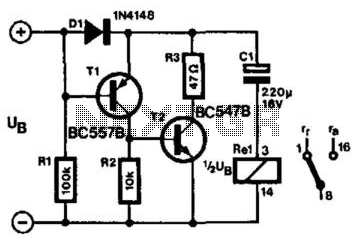
The circuit employs a bistable relay to function in a monostable manner, effectively minimizing the current requirements for operation. The relay operates based on the charging and discharging of capacitor CI, which is pivotal in controlling the state of the relay contacts. When the supply voltage is applied, capacitor CI charges through diode D1 and the relay coil, allowing the current to flow and switch the relay contact to its active state. The forward voltage drop across D1 is crucial, as it ensures that the base of transistor T1 is biased correctly, keeping T1 and T2 in an off state during the initial activation phase.
Upon disconnecting the supply voltage, the circuit configuration changes. The emitter of T1 connects to the positive terminal of CI, while the base connects to the negative terminal through resistor R1 and the relay coil. This configuration induces a condition where T1 turns on, leading to T2 also being activated. As a result, CI discharges through transistor T4 and the relay, reversing the current direction through the relay coil, which triggers the contact to switch over to its alternate position.
The design emphasizes low operational current, with resistor R1 set at 130 ohms, allowing for effective performance without the need for high current supplies, making it suitable for battery-powered applications. The relay coil's voltage rating is critical, recommended to be between 65% to 75% of the supply voltage to ensure reliable operation. In practical implementations, such as the prototype using a 9-V relay with a 12 V battery, this circuit configuration demonstrates an efficient solution for applications requiring a monostable relay function while maintaining low power consumption. A monostable relay has two states: operative when a large enough current flows through its coil and quiesc ent when no current flows. A relay contact that assumes a certain position after the supply voltage has been switched on is required in many applications. Of course, many relays operate in that manner. However, most of these relays require an energizing current of 50 mA or more and that normally precludes a battery supply.
The circuit presented here, which uses a bistable relay, can solve that problem. The contact of a bistable relay normally remains in the position it is in after the supply is switched off. This circuit, however, makes the bistable relay behave like a monostable type, at a modest current. When the supply voltage is switched on, CI charges via Dl and the relay coil. The current then flowing through the coil causes the relay contact to assume one of two positions. The forward drop across Dl ensures that the base of Tl On this condition) is more positive than its emitter so that Tl, and thus T2, is switched off.
When the supply voltage is switched off, the emitter of Tl is connected to the positive terminal of CI, while the base is connected to the negative terminal of the capacitor via Rl and the relay coil. This results in Tl, and thus T2, switching on so that CI discharges via T4 and the relay. The current flows through the relay coil, then flows in an opposite direction and this causes the contact to change over.
The bistable relay thus behaves exactly as a monostable with the advantage, however, that the operational current is determined by Rl, which amounts to only 130 . To ensure reliable operation, the rating of the relay coil should be 65 to 75% of the supply voltage.
In the prototype, a 9-V relay was used with a battery supply voltage of 12 V. 🔗 External reference
Related Circuits
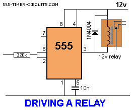
The 555 timer will activate a relay. When pins 2 and 6 are connected as an input, the chip requires only about 1 µA to activate the output. This is equivalent to a gain of approximately 200 million and...
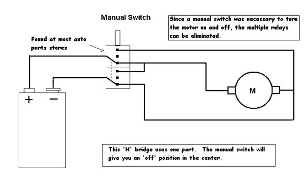
Control a toy car. The toy car is operated via a wired controller, rather than being radio-controlled. The intention is to utilize relays to control the toy through a parallel port. There are various types and models of relays,...
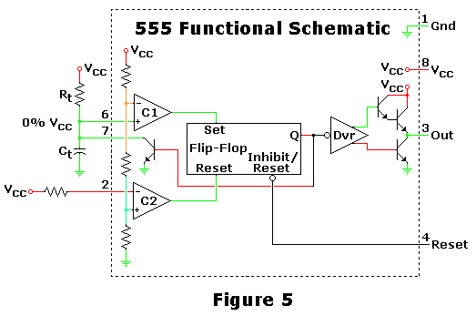
This is one of the most basic 555 circuits. This circuit is part of the chip's datasheet, complete with the math needed to design to specification, and is one of the reasons a 555 is referred to as a...
This device can be interfaced with various adapters, including a keypad adapter (optional), an RF receiver (optional), or via the internet (optional). It can also be adapted to operate with other external attachments. The device features multiple interfacing options, enhancing...
The power windows operate slowly, but connecting 12 volts directly to the motors allows them to function properly. A previous discussion mentioned using a common 5-pin ice cube relay, but there was no confirmation of its effectiveness. The power...
The 4 Channel Infrared (IR) Remote is a straightforward kit that utilizes the well-known HT12A and HT12D encoder/decoder chips from Holtek. The 4 Channel Infrared Remote system is designed for wireless communication, enabling remote control applications in various electronic devices....