
Low-Cost and Simple Intercom

The intercom circuit is designed to facilitate two-way communication between different locations, making it suitable for home or office use. The core components of this circuit include three transistors, which function as amplifiers and switches to control audio signals. The circuit operates on a low voltage, typically between 5V to 12V, ensuring safety and compatibility with common power sources.
Transistor Q1 acts as a microphone amplifier, boosting the audio signals captured by the microphone. The output of Q1 is fed into Q2, which serves as a modulator, converting the audio signals into a form suitable for transmission. The final transistor, Q3, functions as a driver for the speaker, ensuring that the audio output is loud enough for clear communication.
The circuit also includes passive components such as resistors and capacitors, which are essential for biasing the transistors and filtering out unwanted noise. A potentiometer may be incorporated to adjust the volume level of the audio output, providing users with control over the sound.
For assembly, a printed circuit board (PCB) can be utilized to mount the components securely. Proper layout and connections are crucial to minimize interference and ensure reliable operation. The intercom circuit can be housed in a compact enclosure, with the microphone and speaker positioned for optimal performance.
Overall, this intercom circuit design is an excellent project for beginners in electronics, allowing for practical application of fundamental concepts in circuit design and audio processing.This is a low-cost and simple intercom circuit design. Some intercom circuits is build by applying integrated circuits. The circuit described right here utilizes 3 certainly transistors which easy to find on the electronic store. Even a new.. 🔗 External reference
Related Circuits
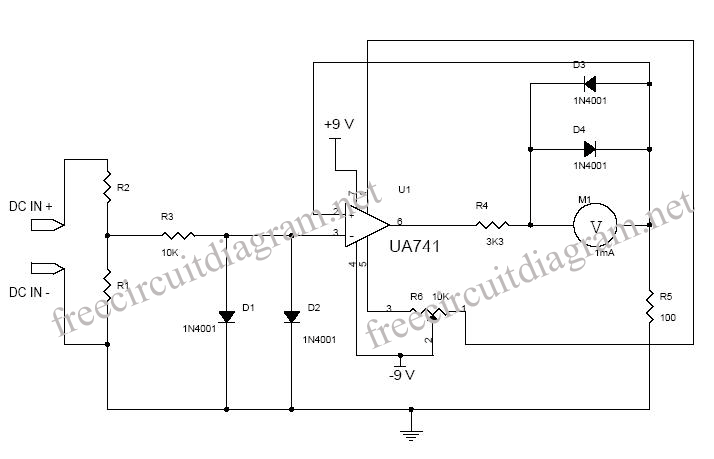
This is a circuit diagram designed for high voltage DC impedance. It utilizes the uA741 integrated circuit (IC), which functions as a non-inverting DC amplifier. The circuit incorporates negative feedback through DC meters to achieve a full-scale deflection of...
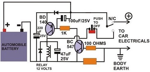
A circuit breaker is an electronic device that functions to protect an electrical circuit from hazards or damage caused by overloads or short circuits. A circuit breaker operates by automatically interrupting the flow of electricity when it detects an...
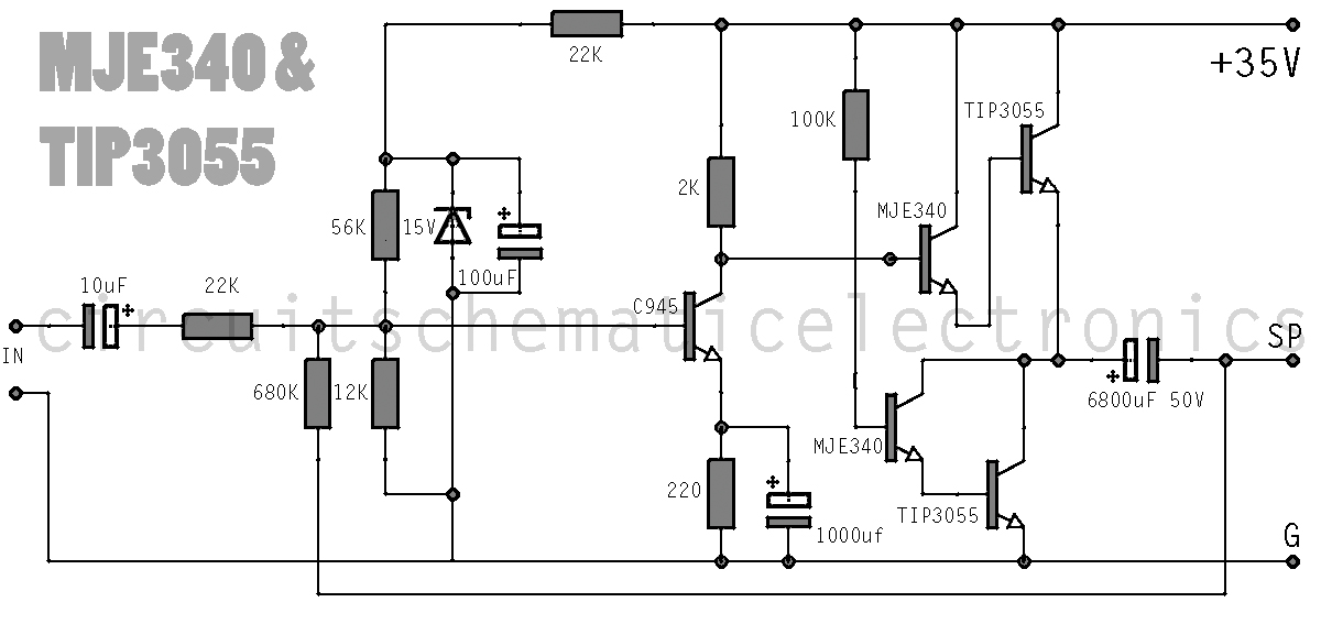
This simple amplifier delivers good sound quality with a power output of approximately 10 to 14 Watts and operates on a supply voltage of about 34 to 36 Volts DC. It requires a preamplifier due to its limited advanced...
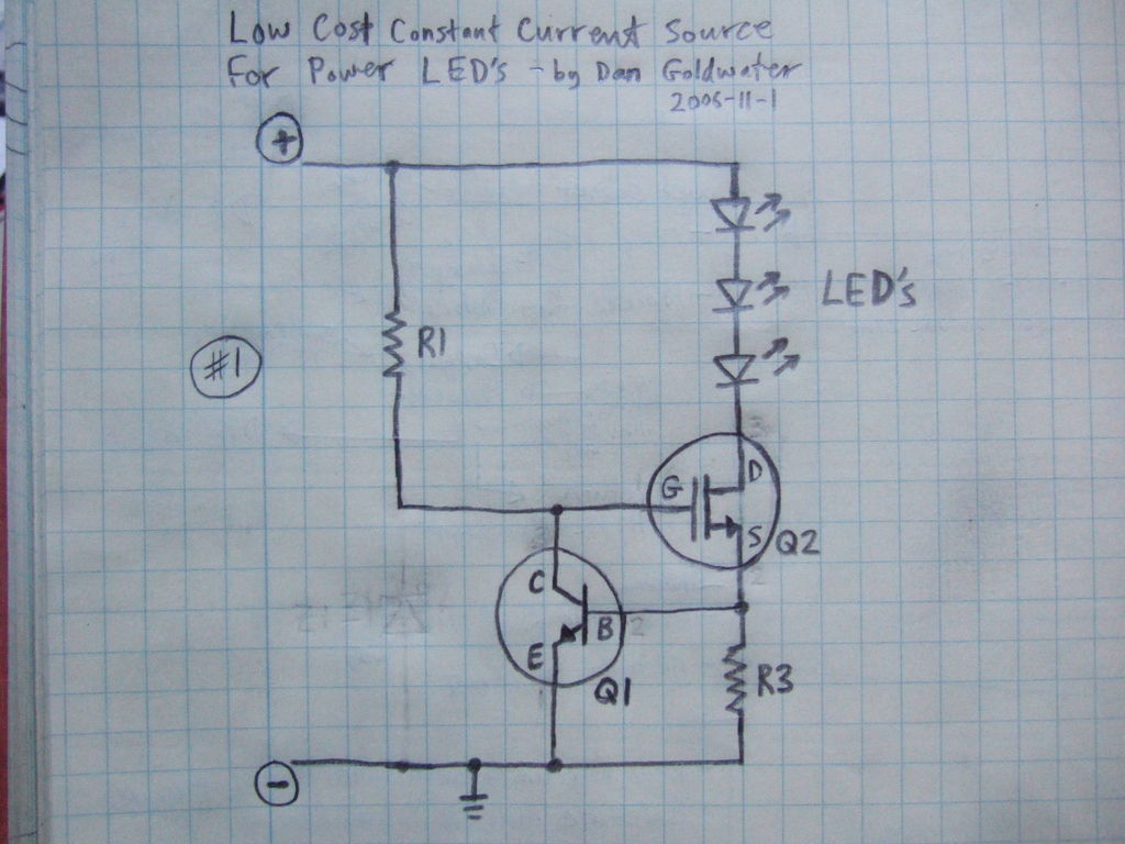
Here is a simple and inexpensive ($1) LED driver circuit. The circuit functions as a constant current source, ensuring that the LED maintains consistent brightness. The LED driver circuit is designed to provide a stable current to the LED, which...
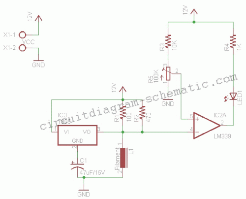
This circuit is a simple air flow detector that signals the presence of air flow. The sensor utilized is a filament incandescent lamp. Components include an air flow detector, a sensor, an LED, and an LM339 operational amplifier. The air...
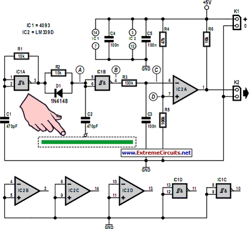
Capacitive touch sensors operate based on the electrical capacitance of the human body. When a finger approaches the sensor, it establishes a capacitance to Earth ranging from 30 to 100 pF. This phenomenon can be utilized for proximity detection...